
Visualization system including data navigator for use with digital computer system

Inactive Publication Date: 2002-07-25
SUN MICROSYSTEMS INC
View PDF0 Cites 3 Cited by
  • Summary
  • Abstract
  • Description
  • Claims
  • Application Information

AI Technical Summary

Benefits of technology

[0005] The invention provides a new and improved arrangement for facilitating the visualization of a selected region of data from a data object, in one of a plurality of predetermined display modes, to facilitate the debugging of a computer program.
[0006] In brief summary, the data visualization arrangement facilitates the display of data items comprising a selected region of an object in a selected one of a plurality of display modes. The arrangement comprises a data object store, an interface, an object region retrieval component and to a display. The data object store stores the data object, the data object comprising a plurality of data items in a predetermined organization. The interface receives a region identification for identifying a particular region of the object and a display mode identification. The object region retrieval component retrieves data items from a region of the data object as identified by the region identification received by the interface. Finally, the display receives the data items as retrieved by the object region retrieval mechanism and displays them in the display mode as identified by the display mode identification.

Problems solved by technology

Verifying that a computer is processing the data in the manner desired by a programmer can be difficult to do, particularly if the program is required to be in any way complex.
While this method may work for some gross errors, it may not be enough to facilitate discovery of all errors, particularly of errors that arise from, for example, errors or eccentricities in the way that the computer itself processes certain program instructions.
In some cases, the amount of data generated by an application program, processed under control of a debugger program, can be quite voluminous.
Easy retrieval of portions of such arrays for display and examination using conventional debugger programs can be fairly difficult.

Method used


Image

  • Visualization system including data navigator for use with digital computer system
  • Visualization system including data navigator for use with digital computer system
  • Visualization system including data navigator for use with digital computer system

Examples


Embodiment Construction

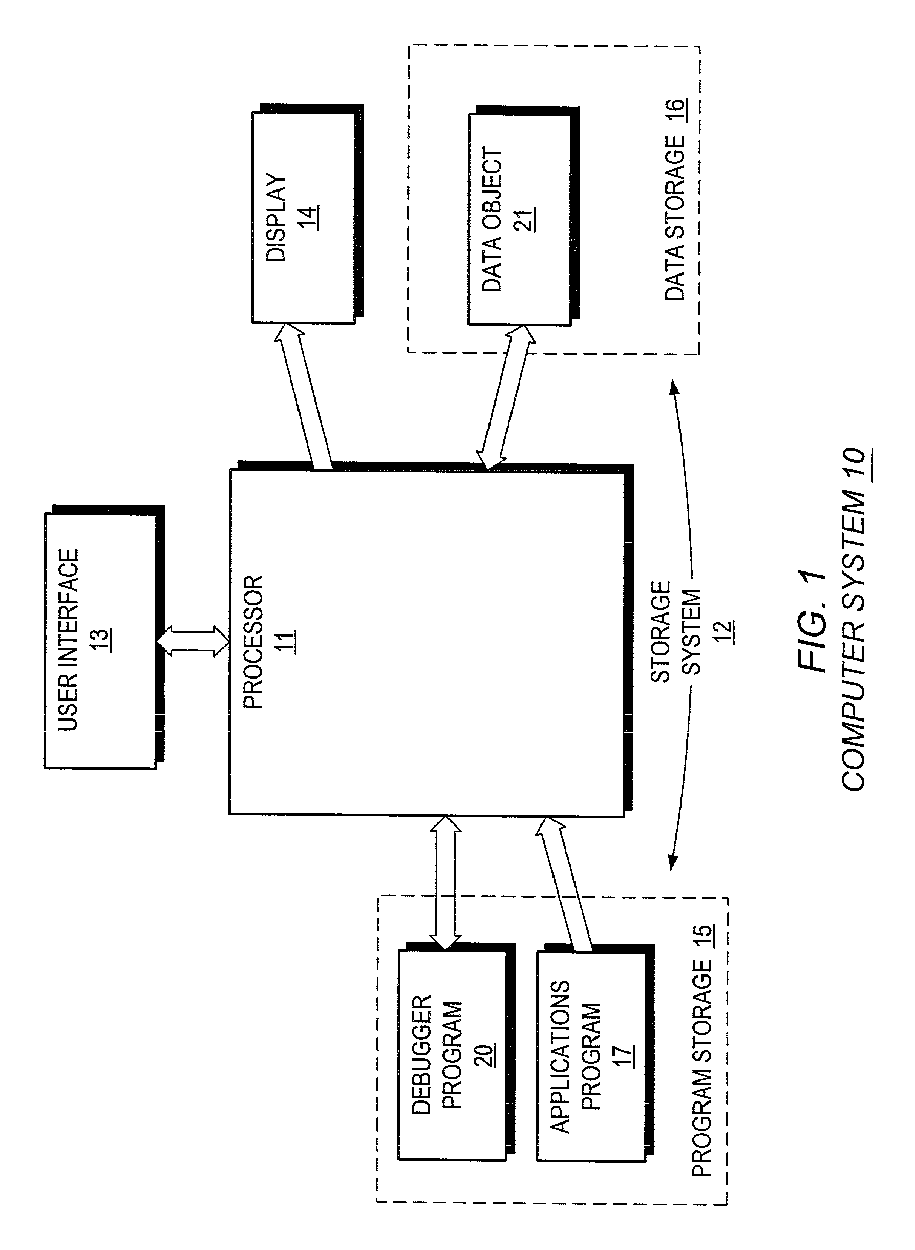
[0014] FIG. 1 is a general functional block diagram showing the new debugger program in the environment of a computer system 10. As is conventional, the computer system 10 includes a processor 11, a storage system 12, a user interface 13 for receiving input from a user via, for example, a keyboard and a pointing device such as a mouse (not shown), and an output device such as video display 14 for displaying output data to the user. The storage system 12 will include a plurality of storage locations which may be divided into a program storage 15 for storing programs for execution and a data storage 16 for storing data. In response to commands received from a user through the user interface 13, the processor 11 executes programs in the program storage 15 to process data (hereinafter "input data") stored in the data storage 16, and generate processed data also for storage in the data storage 16. The processor 11, in response to commands from the user or in response to processing of a p...


PUM


Abstract

A data visualization arrangement for facilitating the display of data items comprising a selected region of an object in a selected one of a plurality of display modes. The arrangement comprises a data object store, an interface, an object region retrieval component and a display. The data object store stores the data object, the data object comprising a plurality of data items in a predetermined organization. The interface receives a region identification for identifying a particular region of the object and a display mode identification. The object region retrieval component retrieves data items from a region of the data object as identified by the region identification received by the interface. Finally, the display receives the data items as retrieved by the object region retrieval mechanism and displays them in the display mode as identified by the display mode identification.

Description

FIELD OF THE INVENTION[0001] The invention relates generally to the field of digital computer systems, and more particularly provides a system and arrangement for facilitating the visualization of data generated by a digital computer system during the processing of a program. The invention is useful in connection with, for example, a debugger program to verify correct operation of another program being debugged with use of the debugger program, as it provides a mechanism for viewing at least a portion of data, either scalar data or data in the form of multi-dimensional arrays, generated during processing of the program being debugged, and also provides a mechanism for easily navigating through the arrays to facilitate viewing of data from diverse regions of the arrays.BACKGROUND OF THE INVENTION[0002] The work of digital computers is controlled by applications programs, which govern the step-by-step operations performed by the computers in processing data. Verifying that a computer ...

Claims


Application Information

Patent Timeline
IPC IPC(8): G06F11/32G06F11/36G06T11/20
CPCG06F11/323G06F11/3664G06T11/206
Inventor ALLEN, DONALD C.BOWKER, RICHARDJOURDENAIS, KAREN C.SIMONS, JOSHUA E.SISTARE, STEVEN J.TITLE, RICHARD
Owner SUN MICROSYSTEMS INC
Learn More