
Generation of debug information for debugging a network security appliance

Inactive Publication Date: 2010-02-09
TREND MICRO INC
View PDF27 Cites 19 Cited by
  • Summary
  • Abstract
  • Description
  • Claims
  • Application Information

AI Technical Summary

Benefits of technology

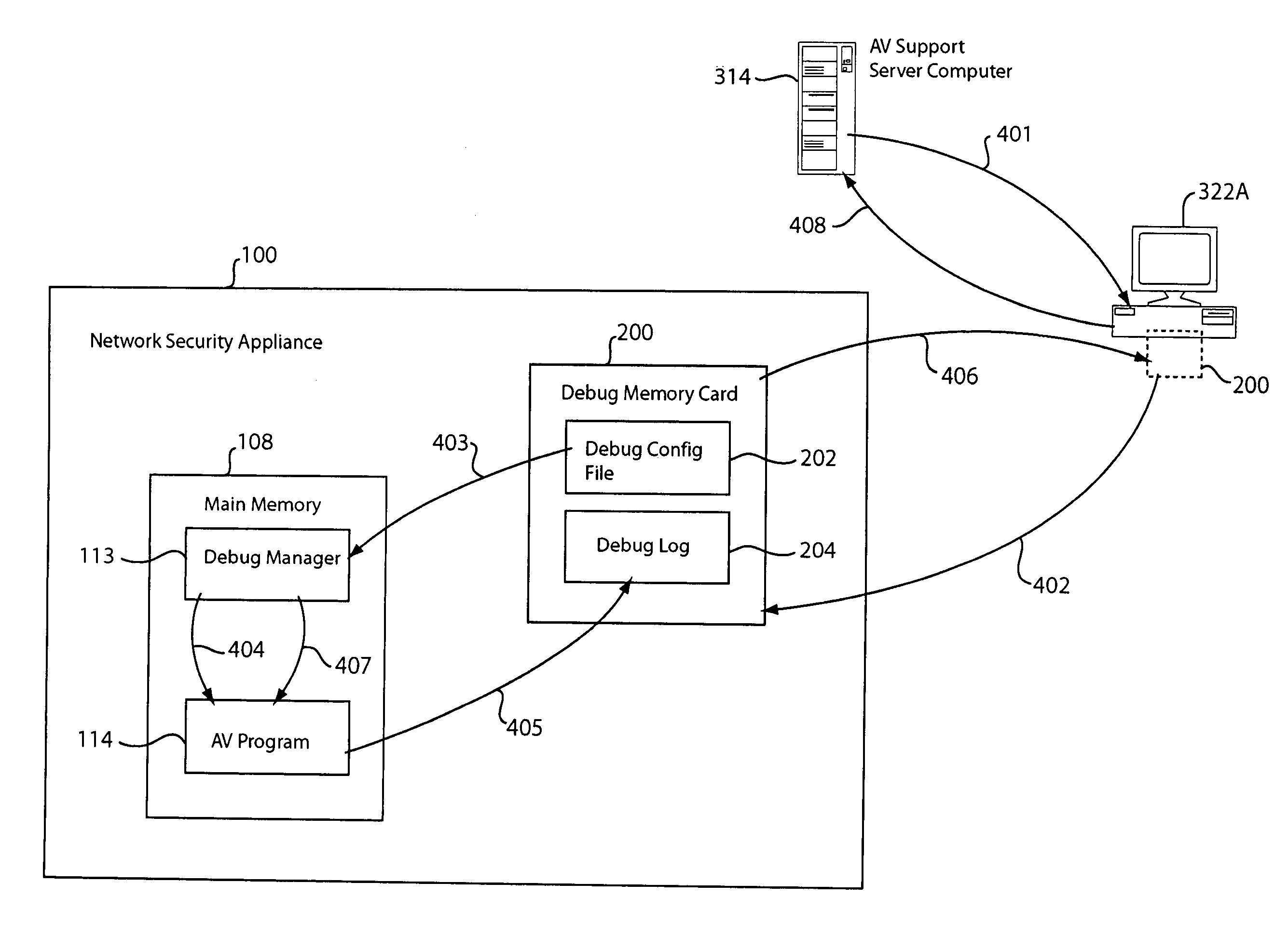
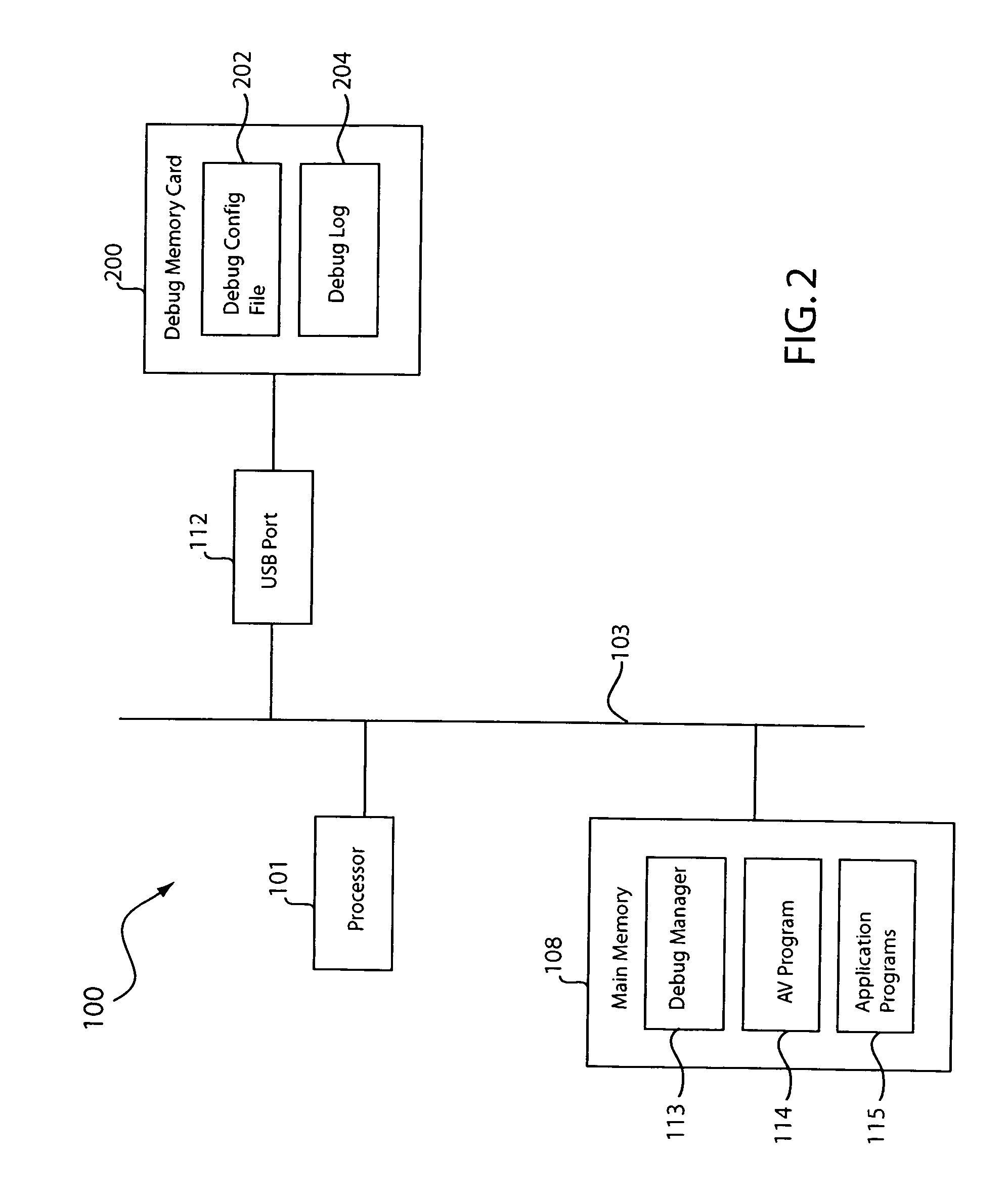
[0005]Debugging of a network security appliance is facilitated by allowing for generation of debug information in a user-friendly manner. In one embodiment, the network security appliance automatically detects a presence of a file in a removable non-volatile memory and, in response, places at least one of its components in debug mode. This allows the component to write debug information to the removable non-volatile memory. Removal of the removable non-volatile memory from the network security appliance automatically triggers placement of the component in non-debug mode. The debug information generated in the network security appliance may be forwarded to a server computer for analysis.

Problems solved by technology

However, even with tight quality control, defective products can and do leave the factory.
This is especially true with relatively complex products like computer systems.
The debugging of computer systems is usually difficult whether at the factory or in the field at a customer site.
However, having to debug the computer system at the customer site is especially difficult given customer expectations and more so when there are no field service personnel available in the area.
To make matters worse, some computer systems, such as network security appliances and other special purpose computers, may be too difficult for the customer to troubleshoot even with remote help from customer service or may not have enough computing resources to facilitate debugging.

Method used


Image

  • Generation of debug information for debugging a network security appliance
  • Generation of debug information for debugging a network security appliance
  • Generation of debug information for debugging a network security appliance

Examples


Embodiment Construction

[0013]In the present disclosure, numerous specific details are provided, such as examples of apparatus, components, and methods, to provide a thorough understanding of embodiments of the invention. Persons of ordinary skill in the art will recognize, however, that the invention can be practiced without one or more of the specific details. In other instances, well-known details are not shown or described to avoid obscuring aspects of the invention.

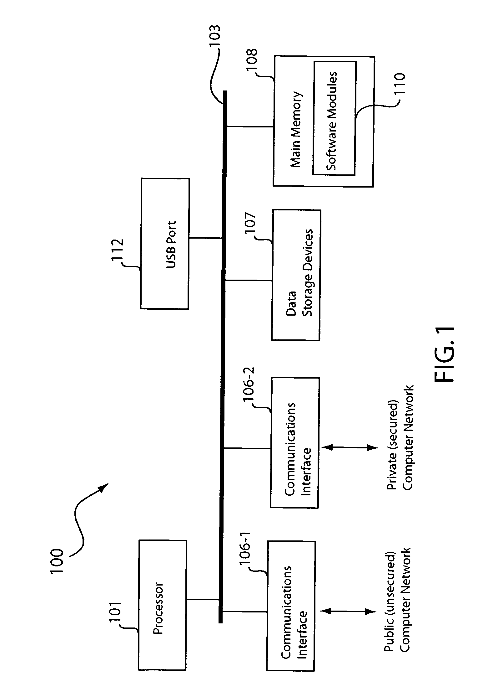
[0014]Being computer-related, it can be appreciated that the components disclosed herein may be implemented in hardware, software, or a combination of hardware and software (e.g., firmware). Software components may be in the form of computer-readable program code stored in a computer-readable storage medium, such as memory, mass storage device, or removable storage device. For example, a computer-readable storage medium may comprise computer-readable program code for performing the function of a particular component. Likewise, computer memo...


PUM


Abstract

Debugging of a network security appliance is facilitated by allowing for generation of debug information in a user-friendly manner. In one embodiment, the network security appliance automatically detects a presence of a file in a removable non-volatile memory and, in response, places at least one of its components in debug mode. This allows the component to write debug information to the removable non-volatile memory. Removal of the removable non-volatile memory from the network security appliance automatically triggers placement of the component in non-debug mode. The debug information generated in the network security appliance may be forwarded to a server computer for analysis.

Description

BACKGROUND OF THE INVENTION[0001]1. Field of the Invention[0002]The present invention relates generally to computer systems, and more particularly but not exclusively to debugging of computer systems in the field.[0003]2. Description of the Background Art[0004]Most manufacturers do their best to ensure that their products work as intended. However, even with tight quality control, defective products can and do leave the factory. This is especially true with relatively complex products like computer systems. The troubleshooting of defective computer systems is also referred to as “debugging.” For example, a defective computer program may be troubleshot by placing it in debug mode. In debug mode, the program writes out debug information, such as register and variable contents, texts and comments placed at certain points of the program, and other information indicative of the internal operation of the program, to a debug log. The contents of the debug log may be displayed on a computer...

Claims


Application Information

Patent Timeline
IPC IPC(8): G06F9/44
CPCG06F11/362
Inventor LEE, JIN-SHI
Owner TREND MICRO INC
Learn More