Self regulating fluid bearing high pressure rotary nozzle with balanced thrust force

a high-pressure rotary nozzle, self-regulating technology, applied in the direction of rotary bearings, shafts and bearings, bearings, etc., to achieve the effect of effective balan

Active Publication Date: 2011-05-12
STONEAGE
View PDF21 Cites 23 Cited by
  • Summary
  • Abstract
  • Description
  • Claims
  • Application Information

AI Technical Summary

Benefits of technology

[0007]A nozzle in accordance with the present disclosure provides a simplified structure which effectively balances any axial thrust force, without ne

Problems solved by technology

There are some applications, however, where offset angled ports are either undesirable due to a change in driving torque when pressure

Method used


Image

  • Self regulating fluid bearing high pressure rotary nozzle with balanced thrust force
  • Self regulating fluid bearing high pressure rotary nozzle with balanced thrust force
  • Self regulating fluid bearing high pressure rotary nozzle with balanced thrust force

Examples


Embodiment Construction

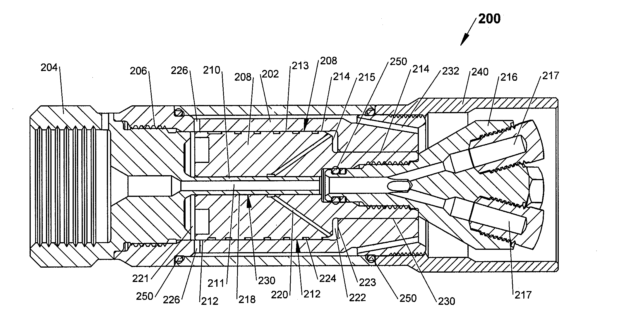
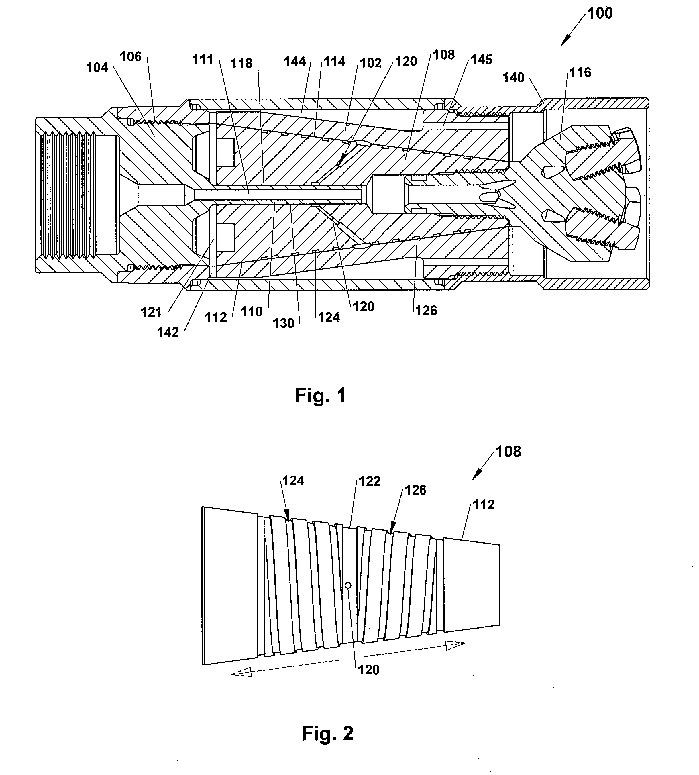
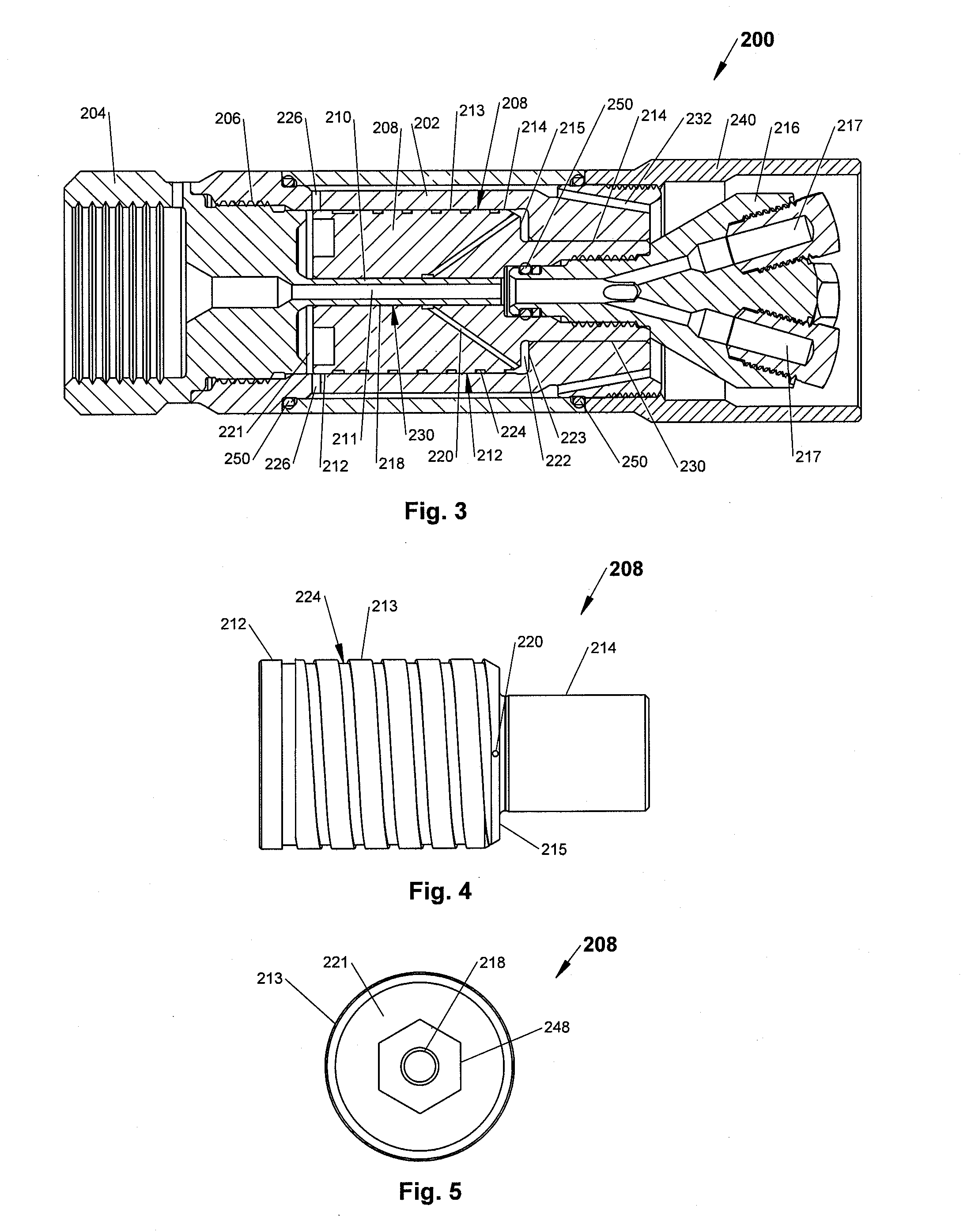
[0021]One embodiment of a nozzle device 100, as is shown in cross section in FIG. 1, has a generally cylindrical overall outer shape so that it can be inserted into pipes and other tubular passages. The device 100 has a hollow tubular body 102 fastened to a high pressure inlet nut 104. The inlet nut 104 is fastened to the body 102 preferably via a threaded connection 106. Captured between the tubular body 102 and the inlet nut 104 is a hollow, tapered, rotatable swivel shaft 108. The shaft 108 is rotatably supported on a tubular stem portion 110 projecting axially out of the inlet nut 104. The outer surface 112 of the shaft 108 has a generally frusto-conical shape that tapers down toward the discharge of the nozzle device 100. The inner surface 118 of the shaft 108 has a cylindrical shape complementary to the stem portion 110 upon which it resides. The inside surface 114 of the tubular body 102 has a frusto-conical tapered shape complementary to the frusto-conical shape of the outer...


PUM


Abstract

A fluid bearing nozzle assembly is disclosed that has a hollow cylindrical body, an inlet nut fastened to the cylindrical body, and a hollow tubular shaft member coaxially carried within the housing body and captured between the inlet nut and the body. The inlet nut has a stem portion extending into a central bore through the shaft member forming an inlet bearing area rotatably carrying the shaft member thereon. The shaft member has a spray head fastened thereto for rotation of the head with the shaft member. An inner wall of the housing body and an outer portion of the shaft have complementary shapes forming a regulating passage therebetween. The shaft has helical grooves that spiral around the shaft to one or both ends to impart rotation to the shaft and spray head.

Description

CROSS-REFERENCE TO RELATED APPLICATIONS[0001]This application claims the benefit of priority to U.S. Provisional Patent Application Ser. No. 61 / 259,944, filed Nov. 10, 2009.BACKGROUND OF THE DISCLOSURE[0002]A high pressure rotary nozzle device having a rotating shaft is disclosed in my U.S. Pat. No. 7,635,096, which is incorporated herein by reference in its entirety. The hollow shaft in this device rotates within a fixed housing wherein the axial force which acts upon the shaft due to the fluid pressure at the shaft inlet is balanced, eliminating the need for mechanical bearings.[0003]This nozzle is particularly well suited to industrial uses where the operating parameters can be in the range of 1,000 to 40,000 psi, rotating speeds of 1000 rpm or more and flow rates of 2 to 50 gpm. The hollow shaft in this device is provided with a “bleed hole” leading from the central bore through the hollow shaft to its exterior. This allows a small portion of pressurized fluid to reach a chamber...

Claims


Application Information

Patent Timeline
IPC IPC(8): B05B3/06
CPCB05B3/002B05B3/0427B05B3/06B05B13/0636F16C17/18B05B15/001F16C17/026F16C17/105B05B13/069B05B15/16
Inventor WRIGHT, DOUGLAS E.
Owner STONEAGE
Why Eureka
Try Eureka