Method and apparatus for optimizing the combustion air system in a recovery boiler
a technology of combustion air system and recovery boiler, which is applied in the direction of lighting and heating apparatus, combustion using lump and pulverulent fuel, combustion types, etc., can solve the problems of reducing the and affecting the combustion efficiency of combustion air system
- Summary
- Abstract
- Description
- Claims
- Application Information
AI Technical Summary
Benefits of technology
Problems solved by technology
Method used
Image
Examples
example 1
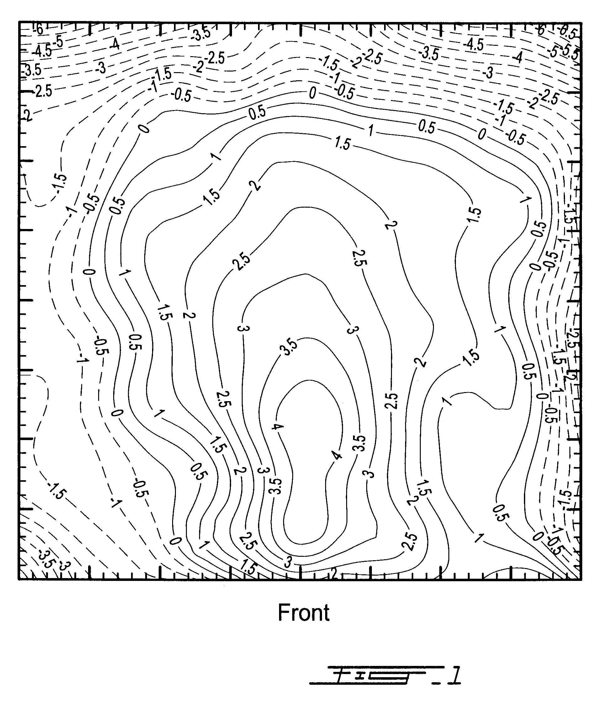
FIG. 1 illustrates a contour plot of the cold flow air velocity profile at the liquor gun level in a typical recovery boiler, "A", whose combustion air system is not optimized. The cold flow air velocities were measured with a standard hot wire anemometer and the flow direction was determined by both an electronic vane-type directional indicator and by visual observation of a mylar ribbon tied to a probe. A computer-based data acquisition system was used to record all air flow velocity data (magnitude and direction). In FIG. 1, a high velocity upward flowing core or chimney is evident adjacent to the front wall of the boiler and is displaced slightly towards the boiler's right wall. In this contour plot, areas with equal velocities are joined. In the areas between contour lines, measured velocities fall between those marked on the adjacent contours.
Boiler A was built in 1990 by Babcock & Wilcox and has a three level combustion air system. While there are three secondary air ports on...
example 2
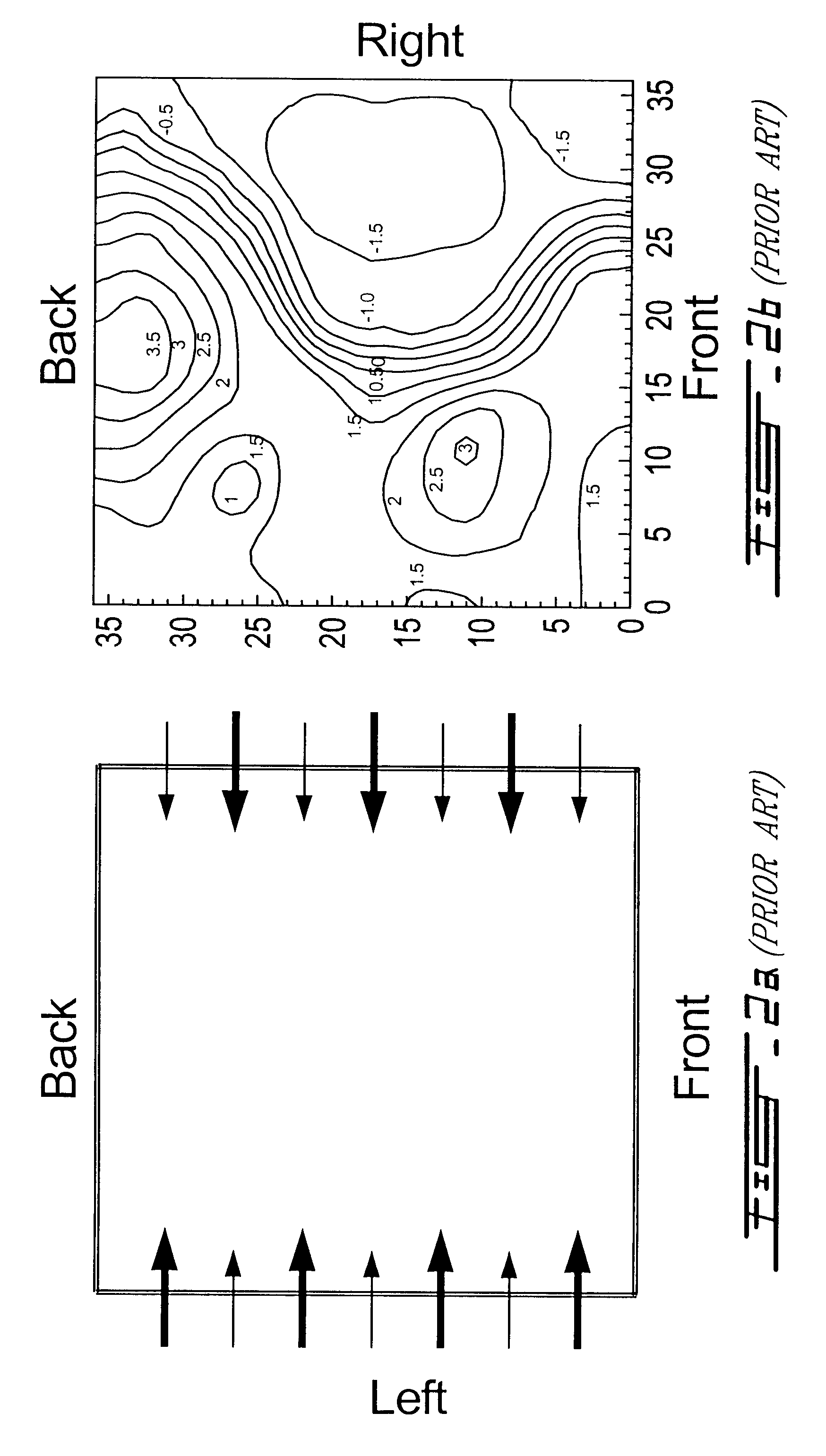
FIG. 2b illustrates a contour plot of the cold air flow velocity profile at the liquor gun level in recovery boiler B. The air system in this boiler was optimized according to the teachings of Blackwell et al., (U.S. Pat. No. 5,121,700), with air flow from all four walls at the primary air level and from the two side walls only at the secondary air level. The secondary air jets were interlaced with large jets versus small, using the sidewall ports only. Load burners on the left and right walls of the boiler opposed each other and both load burners on the right wall were used as "fully open", large ports. The dampers on the other "fully open" ports were opened completely, while those on the "partially open" ports were all half-open. The resulting combustion air distribution between the walls of the boiler, and between the two levels of air injection, is summarized in Table 2. It is apparent that interlacing using this crude approach resulted in twice as much secondary air entering th...
example 3
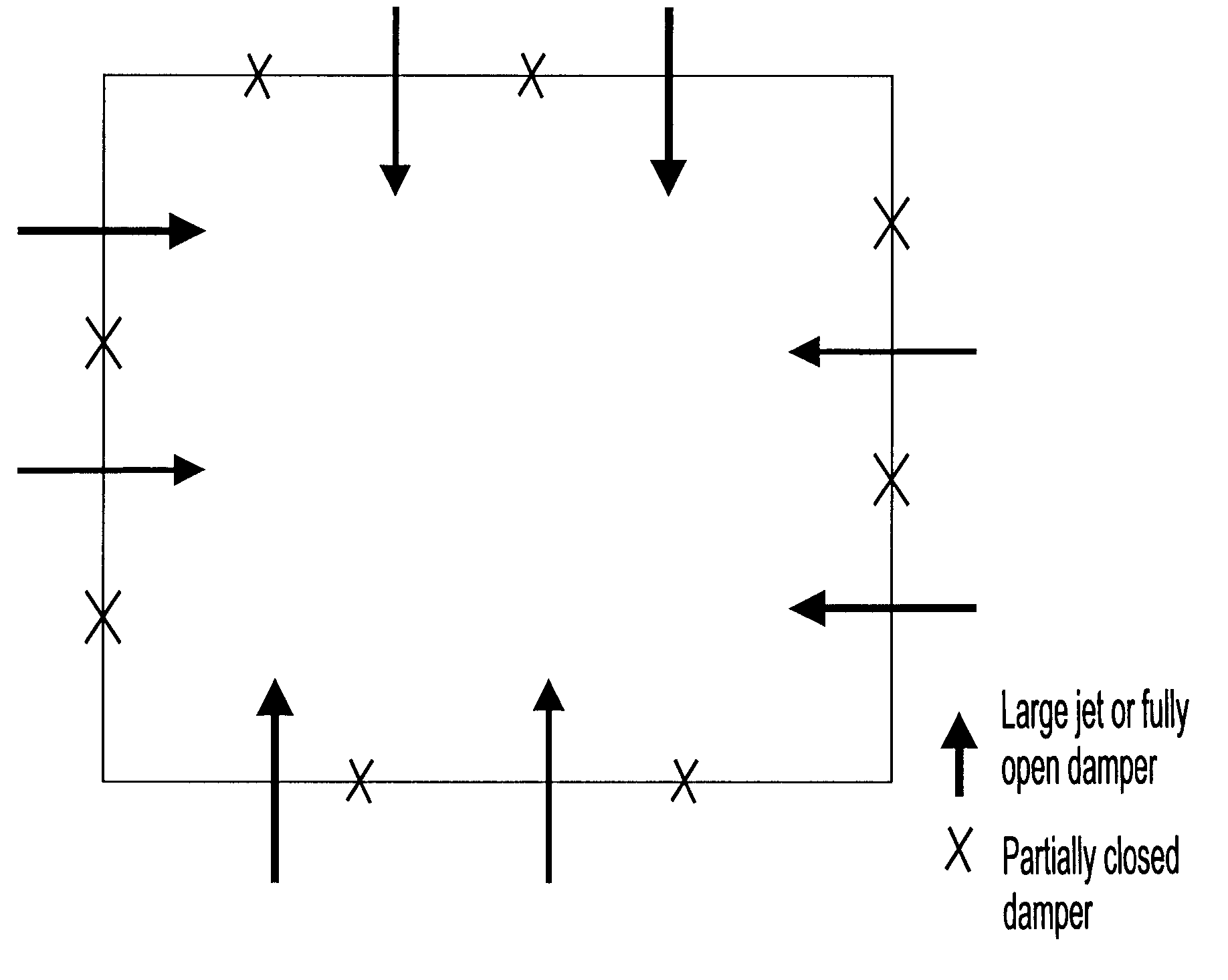
The inventors of the present invention have evaluated air flow patterns in a large number of recovery boilers and have discovered that the introduction of primary air from ports in all four walls invariably creates a high velocity, upward flowing core somewhere in the furnace cross-section. In this evaluation of the potential application of partial (big / small) interlacing of secondary air to reduce the size of the chimney and its peak gas velocities, it was observed that a large percentage of boilers lack the forced draft fan capacity to push the required secondary air flow through only two walls. As a result, contrary to all prior art teachings, the inventors decided to introduce secondary air from opposed ports on all four boiler walls, using the partially interlaced approach described earlier as "interlaced secondary air flow" distributing thE. secondary air equally from each of the four walls, as illustrated in FIG. 3. When the secondary air was distributed to all four walls usi...
PUM
| Property | Measurement | Unit |
|---|---|---|
| Fraction | aaaaa | aaaaa |
| Fraction | aaaaa | aaaaa |
| Fraction | aaaaa | aaaaa |
Abstract
Description
Claims
Application Information
 - R&D
- Intellectual Property
- Life Sciences
- Materials
- Tech Scout
- Unparalleled Data Quality
- Higher Quality Content
- 60% Fewer Hallucinations
Browse by: Latest US Patents, China's latest patents, Technical Efficacy Thesaurus, Application Domain, Technology Topic, Popular Technical Reports.
© 2025 PatSnap. All rights reserved.Legal|Privacy policy|Modern Slavery Act Transparency Statement|Sitemap|About US| Contact US: help@patsnap.com


