
Boiler and the method for controlling combustion of the boiler

a technology of boilers and combustion chambers, which is applied in the direction of combustion regulation, fuel supply regulation, water heaters, etc., can solve the problems of reducing the efficiency of the boiler, increasing the pressure inside the combustion chamber, and reducing the amount of gas supplied, so as to increase the boiler efficiency

Active Publication Date: 2020-07-02
KYUNGDONG NAVIEN
View PDF1 Cites 3 Cited by
  • Summary
  • Abstract
  • Description
  • Claims
  • Application Information

AI Technical Summary

Benefits of technology

The present invention provides a boiler that can determine the clogging degree of its exhaust flue in real time to adjust gas supply and maintain combustibility. The boiler uses pneumatic pressure difference and rotational speed difference to calculate the estimated flue clogging value and the opening amount of the gas valve accordingly, providing appropriate guidance to cope with a fluid clogging situation. The calculation section provides a linear output value to control combustion conditions more precisely. Overall, the boiler is cost-effective and efficient in coping with flue clogging situation.

Problems solved by technology

When the exhaust flue clogging phenomenon occurs, the combustion gas is not discharged smoothly, and thus a pressure inside the combustion chamber is increased and a gas supply amount is reduced to lower the efficiency of the boiler, and a misfire occurs.
As a result, there has been a problem that combustibility in the boiler is lowered.

Method used


Image

  • Boiler and the method for controlling combustion of the boiler
  • Boiler and the method for controlling combustion of the boiler
  • Boiler and the method for controlling combustion of the boiler

Examples


Embodiment Construction

[0033]Exemplary embodiments of the present invention will be described in detail below with reference to the accompanying drawings. While the present invention is shown and described in connection with exemplary embodiments thereof, it will be apparent to those skilled in the art that various modifications can be made without departing from the spirit and scope of the invention.

[0034]Hereinafter, a combustion control method of a boiler according to the present invention will be described in detail with reference to the accompanying drawings.

[0035]Here, the content described in the related art and the overlapping contents will be omitted, and the following description will be made based on components newly added to the present invention.

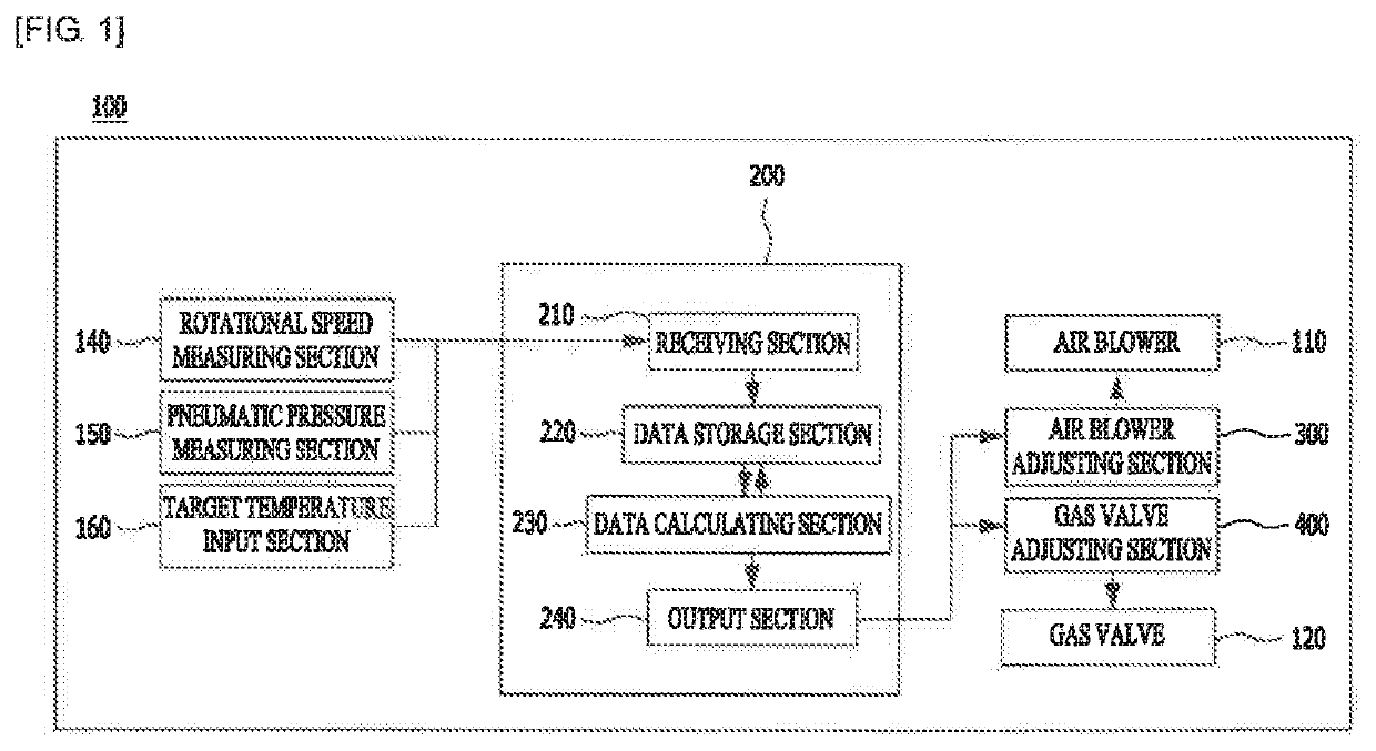
[0036]Referring to FIG. 1, a boiler 100 according to the present invention includes an air blower 110 configured to be rotated such that air and gas are introduced, a gas valve 120 configured to adjust an opening or closing degree of a gas supply pipe...


PUM


Abstract

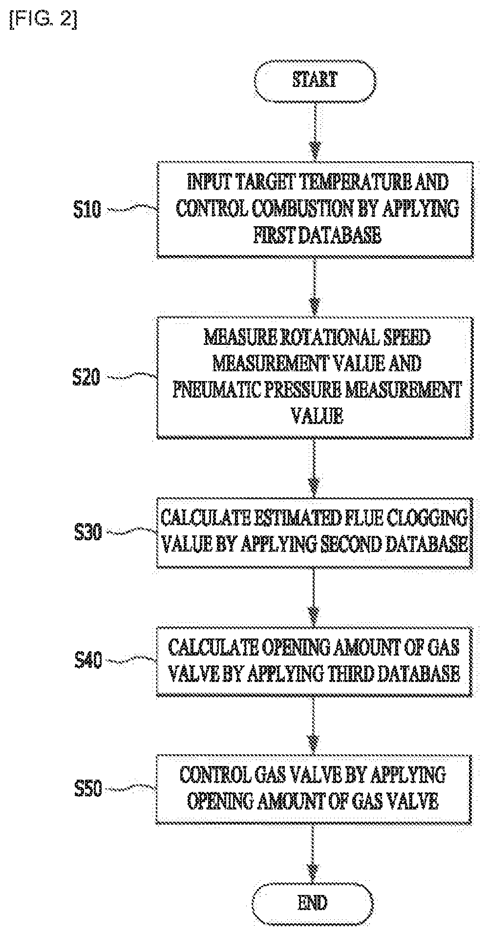
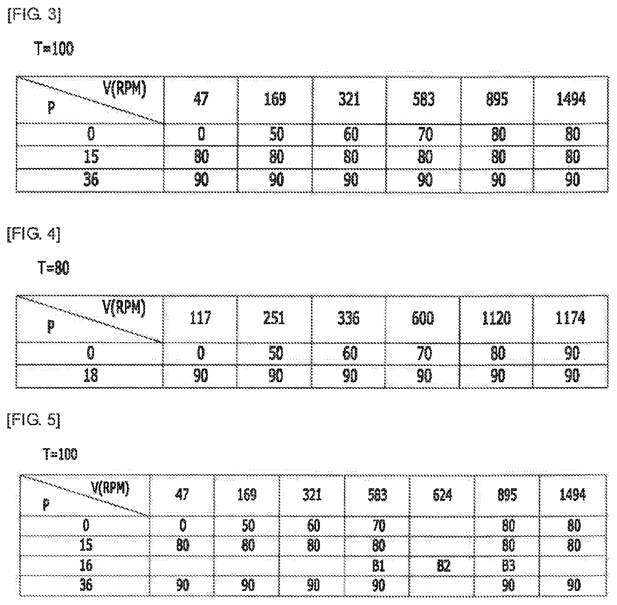
The present invention relates to a boiler which determines a clogging degree of an exhaust flue through which combustion gas is discharged and adjusts gas supply amount to maintain its combustibility, and a combustion control method thereof, the method of the present invention including a) setting a target heat value for achieving a target temperature, b) applying a first database on the basis of the target heat value, c) measuring a rotational speed of an air blower and a pneumatic pressure of air introduced by rotation of the air blow, d) applying a second database on the basis of a rotational speed difference, a pneumatic pressure difference, and the target heat value to calculate an estimated flue clogging value according to the target heat value, and a) applying a third database according to the estimated flue clogging value to calculate an opening amount of a gas valve and control gas supply amount.

Description

CROSS-REFERENCE TO RELATED APPLICATION[0001]This application claims priority to and the benefit of Korean Patent Application No. 10-2018-0171447, filed on Dec. 28, 2018, the disclosure of which is incorporated herein by reference in its entirety.BACKGROUND1. Field of the Invention[0002]The present invention relates to a boiler and a combustion control method of a boiler, and more particularly, a boiler which may determine a clogging degree of an exhaust flue through which combustion gas is discharged and adjust a gas supply amount to maintain combustibility in the boiler, and a combustion control method thereof.2. Discussion of Related Art[0003]In gas boilers using heat generated by combustion of gas as a means for being provided with heating or hot water, an exhaust flue, which is a passage through which burned combustion gas flows and is discharged to the outside, is generally provided.[0004]In this case, the inside of the exhaust flue is corroded by carbon or nitrogen contained i...

Claims


Application Information

Patent Timeline
Patent Type & Authority Applications(United States)
IPC IPC(8): F24H9/20F23N1/02
CPCF23N2231/28F23N2225/04F23N2233/08F23N2239/04F23N2241/04F24H9/2035F23N1/022F23N1/025F24H15/31F24H9/2042F24H15/174F24H15/281F24H15/35F24H15/242F23N1/042F23N5/242F23N2223/54F23N1/005F23N5/22F24H1/00
Inventor CHOI, HYUK
Owner KYUNGDONG NAVIEN
Learn More