Method of and Arrangement for Recovering Heat From Bottom Ash

a bottom ash and heat recovery technology, applied in steam generation using hot heat carriers, combustion processes, incrustation removal devices, etc., can solve the problems of low efficiency, low heat recovery technology, and loss of heat energy in the discharge of the bottom ash, so as to improve recover heat efficiently. , the required investment is very low, and the effect of improving the efficiency of the boiler

Active Publication Date: 2012-11-01
AMEC FOSTER WHEELER ENERGIA
View PDF6 Cites 4 Cited by
  • Summary
  • Abstract
  • Description
  • Claims
  • Application Information

AI Technical Summary

Benefits of technology

[0010]Thus, an object of the present invention is to suggest a novel and an efficient method of cooling down the bottom ash discharged from the furnace.
[0015]The present invention has solved at least some problems relating to the prior art bottom ash cooling systems. For instance, the present invention makes it possible to recover heat efficiently from the bottom ash, and to utilize the recovered heat wherever needed in the power plant.
[0016]The present invention thus makes it possible to improve the efficiency of the boiler significantly. Also, the present invention takes, in any case required, the bottom ash cooling devices or arrangements into more efficient use, whereby the required investment is very low.

Problems solved by technology

Thus, in conventional prior art boilers, the loss of heat energy in the discharge of the bottom ash forms a significant portion of boiler losses.
The heat recovery technology discussed in the above-mentioned patent documents, though teaching the possibility of recovering heat from the bottom ash discharge, is not that efficient.
Especially, when a larger amount of bottom ash is discharged, it is clear that the countercurrent air flow is not able to cool the ash sufficiently.
And, even if additional water spraying is used, there are two risks.
The first is that the ash will not be cooled sufficiently, and secondly, if the ash is cooled sufficiently, there may be too much steam to be introduced into the furnace.
Additionally, mostly due to the inefficiency of air acting as the heat transfer medium, the size of the devices functioning even in a satisfactory manner are very large, and expensive.
And, further, to be able to cool the bottom ash sufficiently, a large amount of air is needed, the use of which as combustion air may interfere negatively with the combustion air system of the boiler.

Method used


Image

  • Method of and Arrangement for Recovering Heat From Bottom Ash
  • Method of and Arrangement for Recovering Heat From Bottom Ash
  • Method of and Arrangement for Recovering Heat From Bottom Ash

Examples


Embodiment Construction

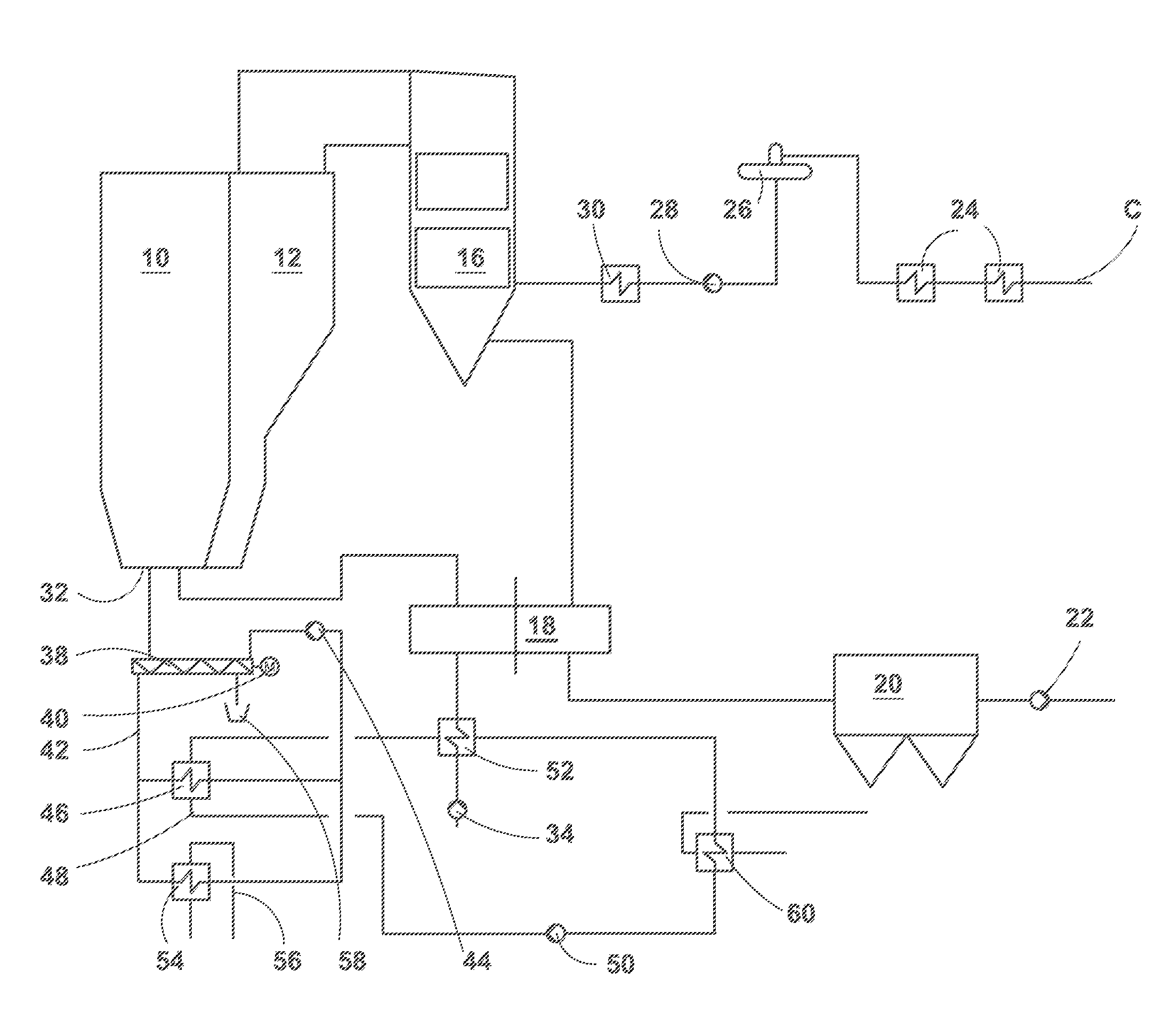
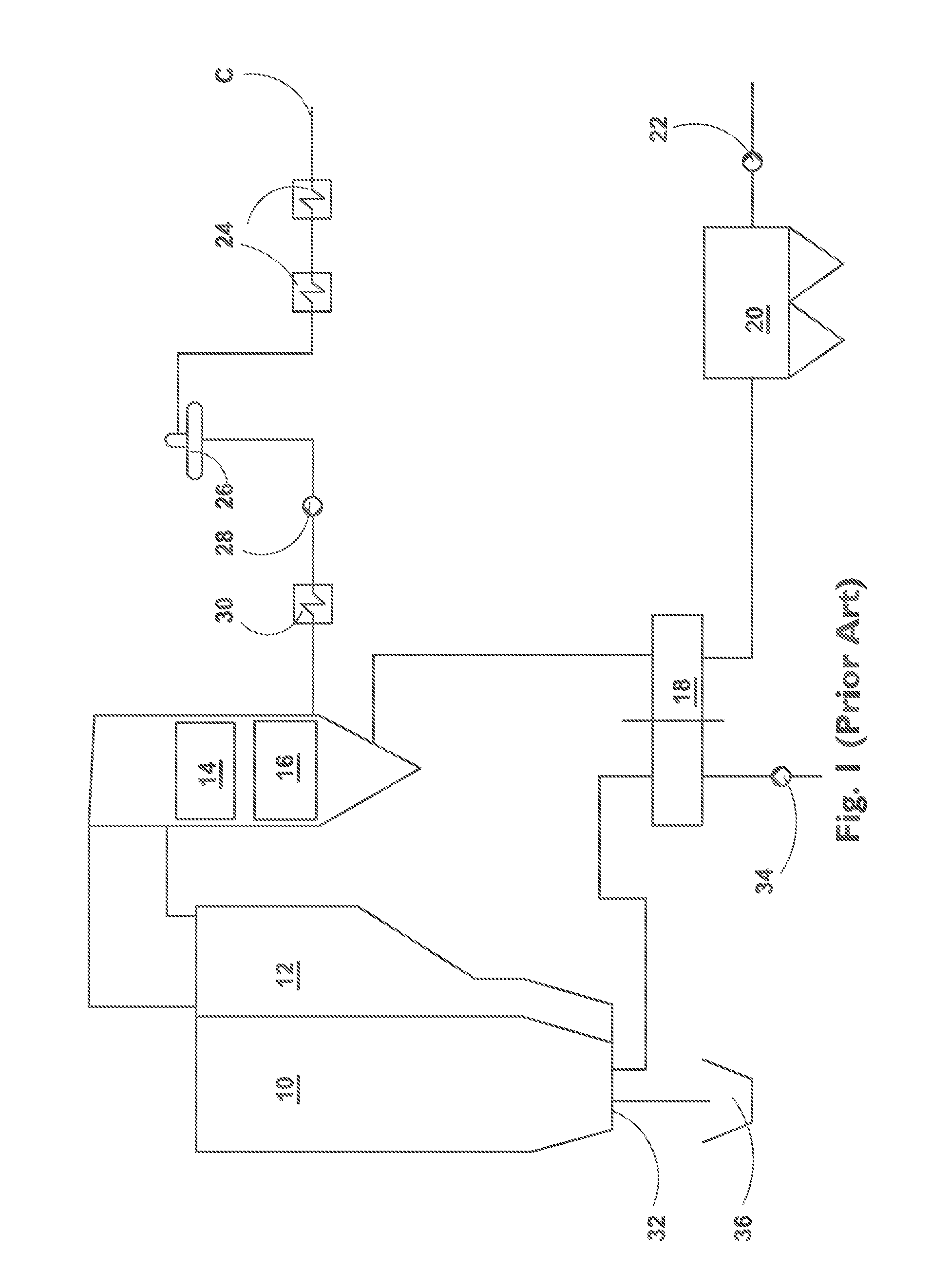
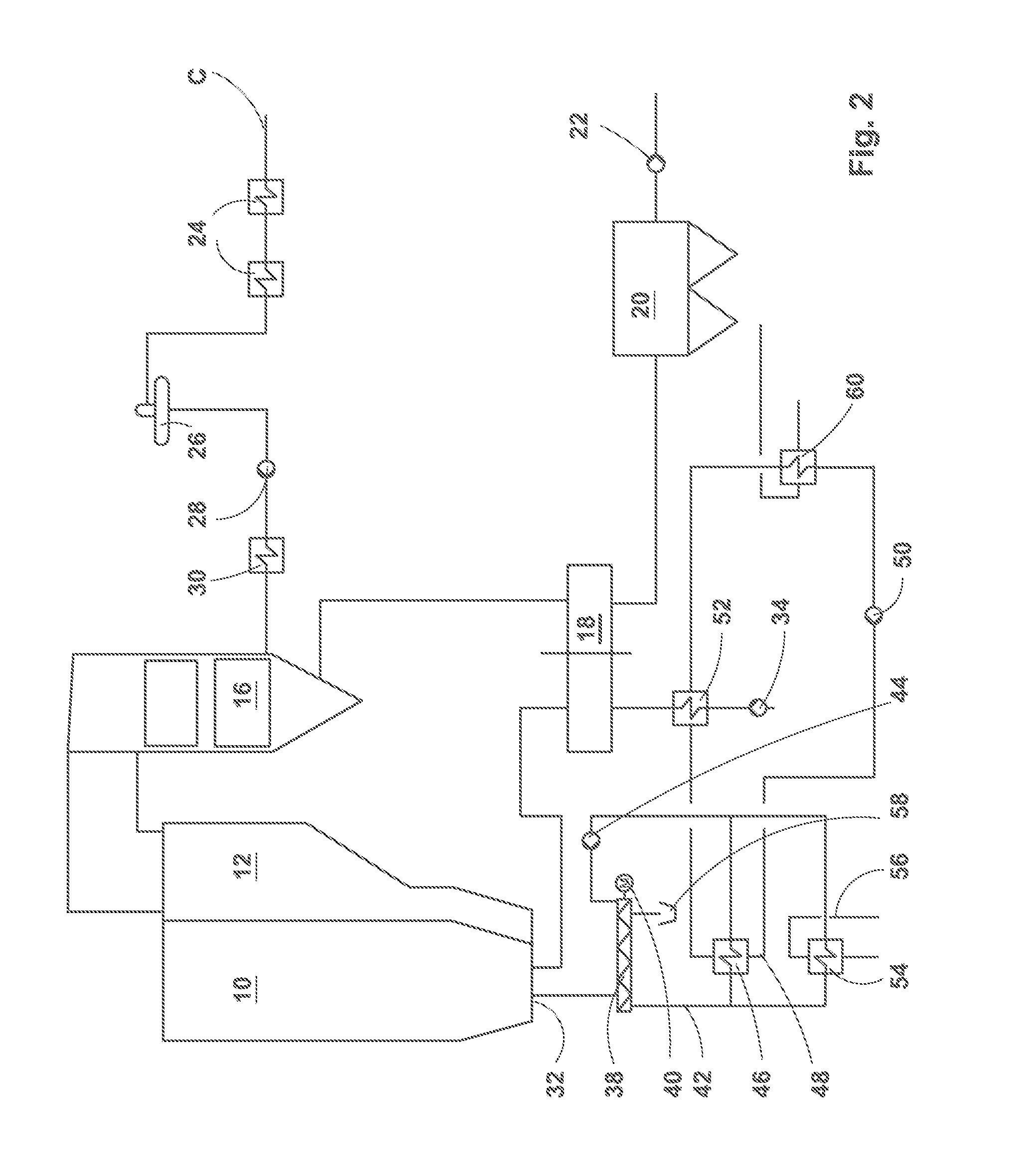
[0023]FIG. 1 schematically illustrates, and, as an example only, an ordinary boiler arrangement of the prior art. A furnace to which the fuel, the bed material and the combustion air are introduced is denoted by reference numeral 10. When combusting the fuel in the furnace 10, heat is generated and both bottom ash and flue gases are formed. The gases are taken to a separator 12, which separates solid particles from the gases, and recirculates the solid particles back to the furnace 10. Both the furnace 10 and the separator 12 are provided with heat exchange surfaces comprising water tubes to collect heat from the flue gases and the solids moving in the furnace 10 and the separator 12. The flue gases are taken from the separator 12 to further heat recovery devices 14, such as superheaters and reheaters, where the heat still available in the flue gases is used to further heat steam. The heat is transferred into use, such as, for instance, for generating electricity by means of steam t...


PUM


Abstract

A method of recovering heat from bottom ash that is discharged from a combustion process in a furnace. Fuel and combustion air are fed into a furnace for combusting the fuel in order to generate heat energy to produce steam or hot water in a boiler arrangement, in which flue gases and bottom ash are formed. The bottom ash is discharged from the furnace. Heat is recovered from the flue gases, and heat is recovered to a bottom ash cooling water circuit from the bottom ash discharged from the furnace in order to utilize the recovered heat for preheating the combustion air in a heat exchanger.

Description

[0001]This application is a U.S. national stage application of PCT International Application No. PCT / FI2010 / 051021, filed Dec. 14, 2010, published as International Publication No. WO 2011 / 076994 A1, and which claims priority from Finnish patent application number 20096376, filed Dec. 21, 2009.FIELD OF THE INVENTION[0002]The present invention relates to a method of and an arrangement for recovering heat from bottom ash of a combustion process performed in a combustion device, from which bottom ash is removed at high temperature. The present invention is specifically applicable to bubbling bed boilers, fluidized bed boilers and circulating fluidized bed boilers.BACKGROUND OF THE INVENTION[0003]An ordinary boiler arrangement of the prior art is comprised of a furnace to which fuel, bed material and combustion air are introduced. When combusting the fuel, heat is generated and both bottom ash and flue gases are formed. The flue gases are taken to a separator that separates solid particl...

Claims


Application Information

Patent Timeline
Patent Type & Authority Applications(United States)
IPC IPC(8): F27D25/00
CPCF22B1/04F23C10/00F23L2900/15041F23J2900/01002F23J1/02Y02E20/34F22B31/08F23C10/24F23L15/00
Inventor RUUSKANEN, MARKO
Owner AMEC FOSTER WHEELER ENERGIA
Why Eureka
Try Eureka