Touch-Sensitive Display Panel

a display panel and touch-sensitive technology, applied in the field of display panels, can solve the problems of heavy and thick electronic products, further jeopardizing the aesthetics of products, etc., and achieve the effect of preventing the interference of the panel and simplifying the structure of the panel

Active Publication Date: 2011-05-12
WINTEK CORP
View PDF3 Cites 45 Cited by
  • Summary
  • Abstract
  • Description
  • Claims
  • Application Information

AI Technical Summary

Benefits of technology

The invention is about a touch-sensitive display panel where the driving circuit and the sensing electrode for touch detection are on the same substrate. This simplifies the structure of the panel and prevents interference between different signals.

Problems solved by technology

The technical problem addressed by this patent is finding ways to make electronic devices that have touch controls more slim and attractive while still providing good functionality.

Method used


Image

  • Touch-Sensitive Display Panel
  • Touch-Sensitive Display Panel
  • Touch-Sensitive Display Panel

Examples


Embodiment Construction

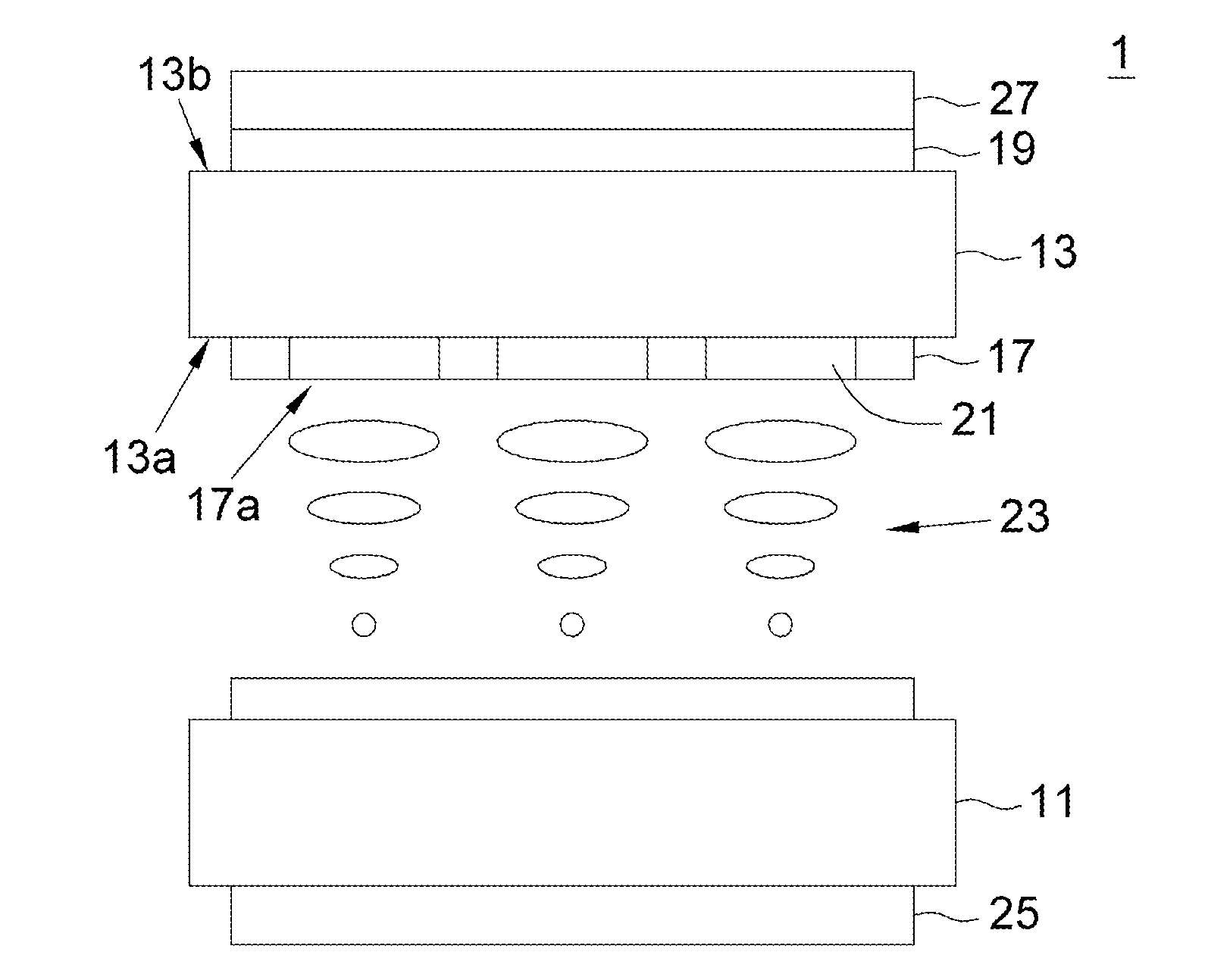
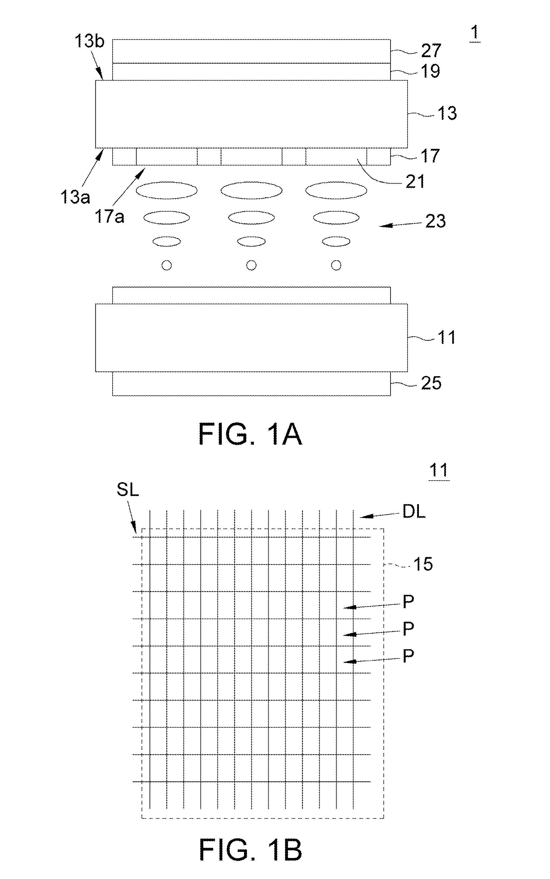
[0021]Referring to FIG. 1A, 1B. FIG. 1A shows a touch-sensitive display panel according to a preferred embodiment of the invention. FIG. 1B shows the disposition of the signal lines of the touch-sensitive display panel of FIG. 1A. The touch-sensitive display panel 1 includes a first substrate 11, a second substrate 13, an active pixel matrix 15 (illustrated in FIG. 1B), a plurality of driving circuits 17, a plurality of sensing electrodes 19 and a plurality of color filter layers 21. The active pixel matrix 15 disposed on the first substrate 11 includes a plurality of elements such as scan lines SL, data lines DL and pixels P. The second substrate 13 parallel to the first substrate 11 has a first surface 13a and a second surface 13b, wherein the first surface 13a faces the active pixel matrix 15 disposed on the first substrate 11.

[0022]The driving circuits 17 are distributed on the first surface 13a of the second substrate 13, and the sensing electrodes 19 are distributed on the sec...


PUM


Abstract

A touch-sensitive display panel including a first substrate, a second substrate, an active pixel matrix, many driving circuits, many sensing electrodes and many color filter layers is provided. The active pixel matrix includes many pixels. The second substrate has a first surface and a second surface, wherein the first surface faces the active pixel matrix. The driving circuits are corresponding to the edges of the pixels for forming many openings. Each driving circuit includes a first main line and a second main line. The first main line has a first end connected to the active pixel matrix and a second end connected to the first substrate. The second main line is connected to the second end of the first main line through the first substrate. The color filter layers are filled in the openings. The sensing electrodes and the driving circuits are used for detecting at least one touch point.

Description


Claims


Application Information

Patent Timeline
Owner WINTEK CORP
Why Eureka
Try Eureka