
Method and computer implemented apparatus for controlling a lighting infrastructure

a technology of lighting infrastructure and control device, applied in the direction of electric controllers, ignition automatic control, instruments, etc., can solve the problems of increasing the number of controls, the insufficient use of simple control tools such as switches or dimming wheels, and the inability of people to create desired lighting atmospheres, etc., to achieve the effect of easy and intuitive control

Active Publication Date: 2011-05-12
KONINKLIJKE PHILIPS ELECTRONICS NV
View PDF4 Cites 43 Cited by
  • Summary
  • Abstract
  • Description
  • Claims
  • Application Information

AI Technical Summary

Benefits of technology

The present invention provides a method and computer-implemented apparatus for controlling a lighting infrastructure in a room. The method involves creating a single room view of the room by combining different views of the room with lighting effects, and receiving and processing input signals with regard to the generated single room view. The invention allows users to create desired lighting effects in the room with a single room view, similar to creating a computer paint program. The invention also provides a computer model of the lighting infrastructure to facilitate the creation of control signals for the lighting units. The technical effects of the invention include making it easier and more intuitive for users to create and control lighting scenes or atmospheres in a room.

Problems solved by technology

The increase in possibilities is at the cost of an increase in the amount of controls.
For a complex lighting infrastructure with a plurality of different light units or lamps, simple control tools like switches or a dimming wheel will not be sufficient for people to create desired lighting atmospheres.
All these tools are known to the user, but these control devices can only influence a single lamp, or a group of lamps.
And the user is limited to recall the pre-programmed scenes only.

Method used


Image

  • Method and computer implemented apparatus for controlling a lighting infrastructure
  • Method and computer implemented apparatus for controlling a lighting infrastructure
  • Method and computer implemented apparatus for controlling a lighting infrastructure

Examples


Embodiment Construction

[0041]In the following, functionally similar or identical elements may have the same reference numerals.

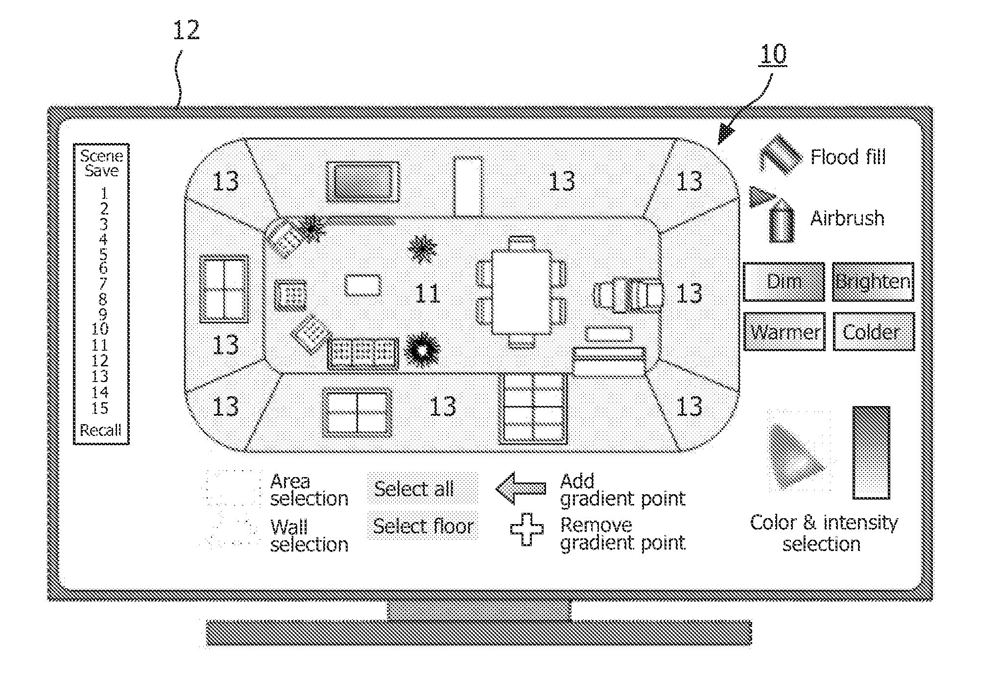
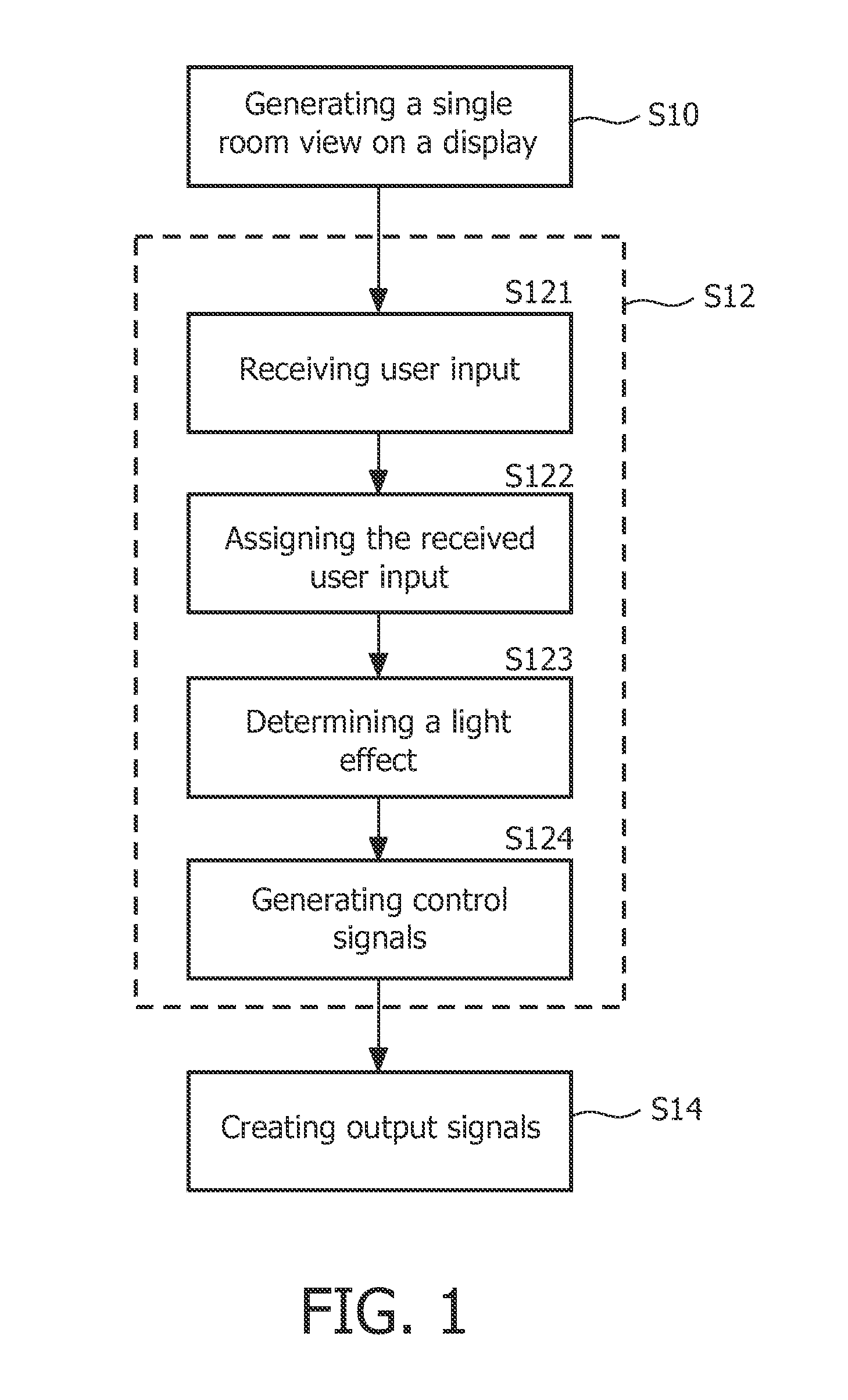
[0042]FIG. 1 shows a flowchart of a method for controlling a lighting infrastructure by means of a computer-implemented apparatus that uses a single view on a room where the lights have to be controlled by creating color and intensity distributions in the view. The apparatus can be a computer, tablet PC or handheld computer, but also simpler embodiments (like a photo-frame) can be used as user interface. The method is implemented as a computer program, which is executed by apparatus.

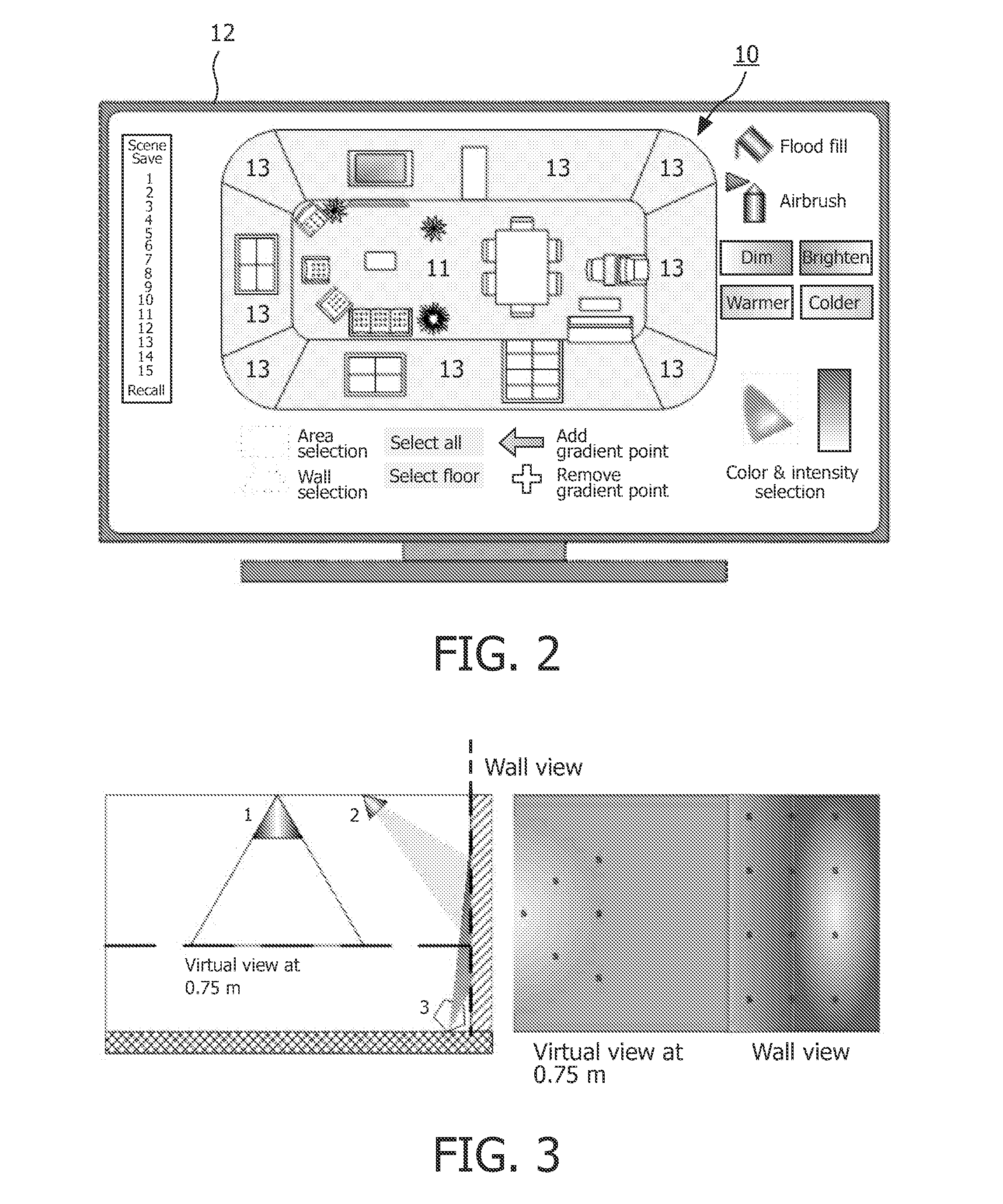
[0043]The computer program is adapted to generate the single view on a room or briefly called a single room view 10 (FIG. 4) of a room with the lighting infrastructure 20 by combining different views of the room on a display such as a computer monitor 12 (step S10 of the flowchart). The single room view 10 may be generated by reading in data regarding the room with the lighting infrastructure 20, for e...


PUM


Abstract

The invention relates to the control of a lighting infrastructure such as a complex lighting system. An embodiment of the invention provides a method for controlling a lighting infrastructure by means of a computer comprising the acts of generating a single room view (10) of a room with the lighting infrastructure by combining different views of the room on a display (12; S10), —receiving and processing of input signals (14) with regard to the generated single room view (S12), and —creating output signals (16) for controlling the lighting infrastructure in response to the processed input signals (S14). The single room view allows an intuitive control of a lighting infrastructure similar to a computer paint program.

Description

FIELD OF THE INVENTION[0001]The invention relates to the control of a lighting infrastructure such as a complex lighting system.BACKGROUND OF THE INVENTION[0002]With the introduction of LED (Light Emitting Diode) based lighting in home and professional environments, people will have the possibility to create and change the perceived atmosphere of the environment. People know the possibility of dimming the lighting level and switching on spotlights to increase the coziness in the environment. On short term, they will have the possibility to create more atmospheres by using LED lighting on walls and objects, by changing the color temperature of the ambient lighting in the room, or by creating spots of lights to support their activities. The increase in possibilities is at the cost of an increase in the amount of controls. For a complex lighting infrastructure with a plurality of different light units or lamps, simple control tools like switches or a dimming wheel will not be sufficien...

Claims


Application Information

Patent Timeline
Patent Type & Authority Applications(United States)
IPC IPC(8): G05B15/02
CPCH05B37/029H05B37/02H05B45/18H05B45/20H05B47/10H05B47/155H05B45/10
Inventor ENGELEN, DIRK VALENTINUS RENE
Owner KONINKLIJKE PHILIPS ELECTRONICS NV
Learn More