Method and device for aiding the monitoring of a turbine engine of an aircraft

a technology for aircraft turbine engines and monitoring devices, which is applied in the direction of machines/engines, instruments, navigation instruments, etc., can solve the problems of no easy pre-sample sounding method for crew, etc., and achieve the effect of quick gain of precise impression of the state of the aircraft and intuitive start of the monitoring of the turbine engin

Active Publication Date: 2015-11-24
AIRBUS OPERATIONS (SAS) +1
View PDF6 Cites 2 Cited by
  • Summary
  • Abstract
  • Description
  • Claims
  • Application Information

AI Technical Summary

Benefits of technology

[0026]Therefore, when looking at the indicating elements displayed, an operator is able to quickly ascertain the state of the engine (rotation, temperature) and thus the characteristics of sub-idle operation, particularly upon start (hung, quick or hot start, etc.) and during an attempt to recover from sub-idle operation.
[0034]In a first, preferred embodiment allowing, in particular, easy reading, said first, second and third indicating elements correspond respectively to a needle which moves on a dial which is graduated in terms of the percentage to which start is complete, to a first main (lower) movable boundary marker of a first main segment of this dial which represents an overheating limit (possibly accompanied by an auxiliary segment associated with a second overheating limit), and to a second main (lower) movable boundary marker of a second main segment of this dial which represents a hung-start limit.
[0076]The present invention thus relates to the creation and display of new parameters for monitoring an aeronautical turbine engine in a sub-idle operating phase, in particular while starting-up. The purpose of displaying these new parameters is to make the monitoring of a turbine engine start more intuitive and easier, by helping the crew to focus on simple parameters, reduced to a bare minimum and allowing the pilot(s) to have a phase lead over the system. Moreover, by extending this display to all the sub-idle operating phases, and by using different symbols for an engine in standard operation (conventional display) and an engine in sub-idle operation (display according to the invention), the crew can very quickly gain a precise impression of the state of the aircraft, by unambiguously segregating the turbine machines in standard operation from those not able to provide propulsion.

Problems solved by technology

As a criterion, this temperature limit depending on the rotational speed is closer to the physical reality of the turbine engine; however, the crew cannot memorise it since it changes (and is therefore not published in the operating manuals).
This variable limit is taken into account by the warning logics of the turbine engine control unit, but the crew has no means of easily anticipating the sounding of an overheating warning or a start failure and generally simply has to react if the need arises.

Method used


Image

  • Method and device for aiding the monitoring of a turbine engine of an aircraft
  • Method and device for aiding the monitoring of a turbine engine of an aircraft
  • Method and device for aiding the monitoring of a turbine engine of an aircraft

Examples


first embodiment

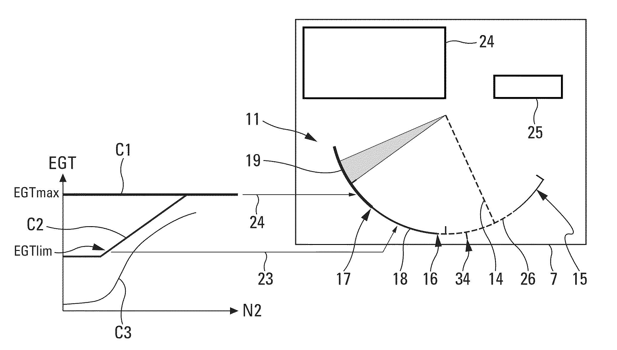
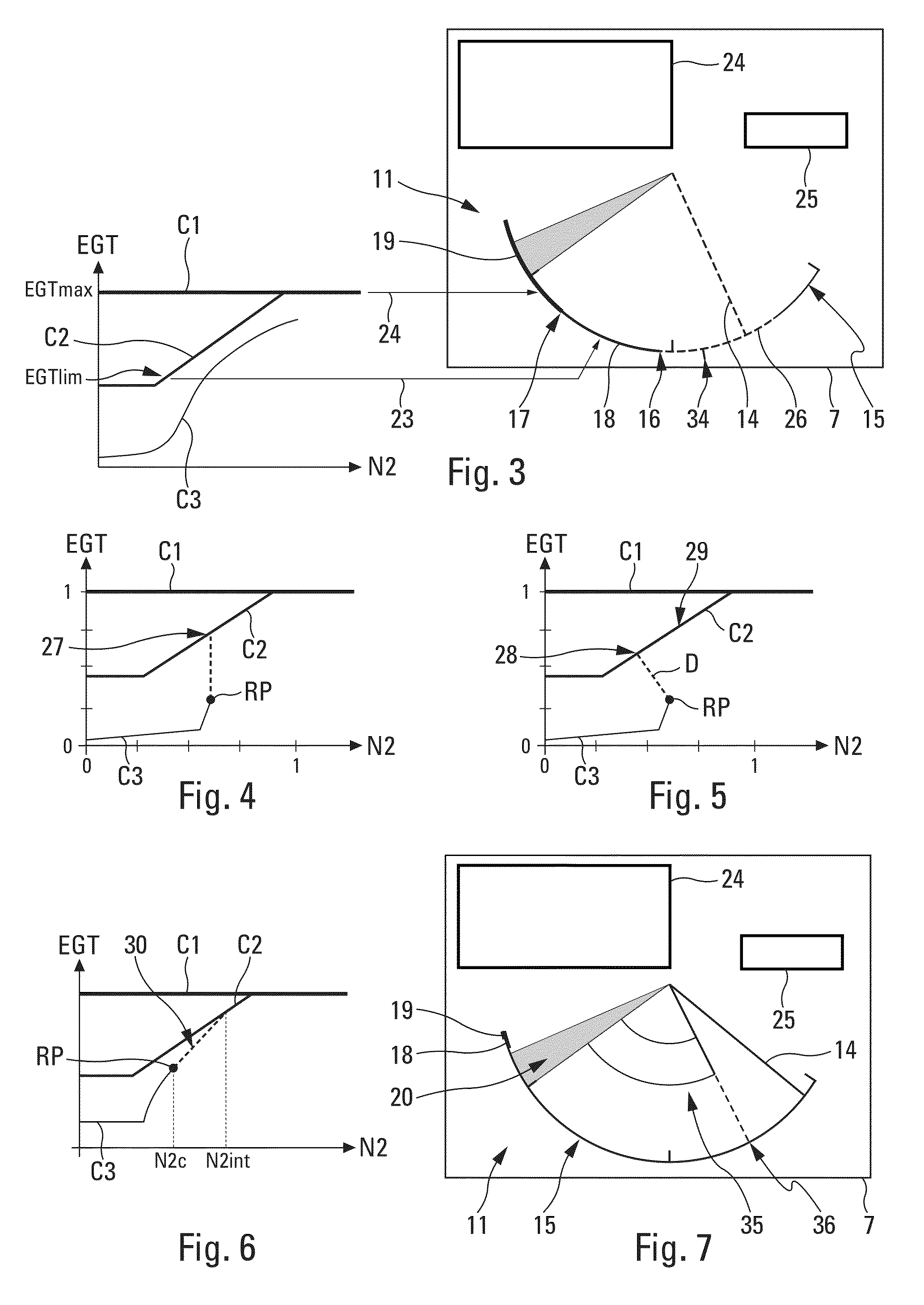
[0114]In this first embodiment, said calculation means 3 calculate the value P2 for the movable boundary marker 16, 17 on said dial 15, using the following expression:

P2=(N2c+k1×ΔN2ant+(1−k1)×ΔEGTrN2) / N2ld

in which, in addition to N2c and N2ld: [0115]ΔEGTrN2 gives the margin with respect to an EGT limit (as set out below) at the current operating point;[0116]ΔN2ant indicates an anticipated breach of the overheating limit, at current dynamics; and[0117]k1 is a coefficient of empirical adjustment between the anticipation term ΔN2ant and the current margin term ΔEGTrN2 which is used to weight the anticipation term with respect to the current margin term to obtain an accurate forecast, taking into account the crew response time.

[0118]The EGT limit taken into account may correspond:[0119]either to a published set maximum overheating limit EGTmax;[0120]or to a variable overheating limit EGTIim which depends on the value of N2 and which is determined in the conventional manner.

[0121]At the...

case 1

A / case 1: ΔEGTrN2≦0

[0141]Since the margin towards the EGT limit is already negative, there is no point calculating an anticipation factor. In addition, it is assumed that ΔN2ant=0 ;

case 2

B / case 2: ΔEGTrN2>0 , dEGT / dt≧0 and dN2 / dt≧0

[0142]The value at the intersection can be determined using the equation below:

N2int=(EGTc−N2c×(dEGT / dN2)c−f) / (d−(dEGT / N2)c

[0143]in which d and f are taken from the equation y=d.x+f of the curve C2 indicating the EGT limit.

[0144]To avoid an infinite value, N2int will be limited to an arbitrary empirical value MaxN2int;


PUM


Abstract

A method and device for aiding the monitoring of a turbine engine of an aircraft, which displays on one and the same indicator of a of a display indication elements illustrating as a percentage the engine start progression or the current sub-idle state of the turbine engine, a margin to a limit temperature of the turbine engine, a margin to a maximum temperature of the turbine engine and a margin to a possible failure of the start that is generated by a too low speed increase of the turbine engine.

Description

RELATED APPLICATION[0001]This application claims priority to France Application No. 12 61338, filed Nov. 28, 2012, the entire contents of which is hereby incorporated by reference.BACKGROUND OF INVENTION[0002]The present invention relates to a method and a device for aiding the monitoring of a turbine engine of an aircraft, in particular of a transport aeroplane, while said turbine engine is in a sub-idle operating phase.[0003]“Sub-idle operation” relates to an operating state of the turbine engine, particularly during the start phase or during recovery after an ill-timed dip below the lowest power ensuring stable operation, for which the turbine engine rotates more slowly than when it is idling.[0004]Generally, to monitor the start or reacceleration towards idle speed of the engines of an aircraft, the aircraft crew is obliged to check several digital and / or analogue parameters simultaneously, which are displayed on various screens or instruments (particularly on a main ECAM page a...

Claims


Application Information

Patent Timeline
Patent Type & Authority Patents(United States)
IPC IPC(8): G01C21/00B64D45/00B64D43/00F02C9/00
CPCB64D45/00B64D43/00F02C9/00F05D2260/80F05D2260/85G01D2207/10
Inventor COTTET, JEAN-PHILIPPEPATRIS, HUBERTBIRNFELD, MANFREDPERRIN, PHILIPPEDUCARROIR, STEPHAN
Owner AIRBUS OPERATIONS (SAS)
Why Eureka
Try Eureka