Parallel robot

a robot and parallel technology, applied in the field of parallel robots, can solve the problems of high cost of decelerator, difficult maintenance, complex construction of decelerator,

Inactive Publication Date: 2011-05-19
HONG FU JIN PRECISION IND (SHENZHEN) CO LTD +1
View PDF15 Cites 25 Cited by
  • Summary
  • Abstract
  • Description
  • Claims
  • Application Information

AI Technical Summary

Problems solved by technology

However, the decelerator has a high cost.
In addition, the decel

Method used


Image

  • Parallel robot
  • Parallel robot
  • Parallel robot

Examples


Embodiment Construction

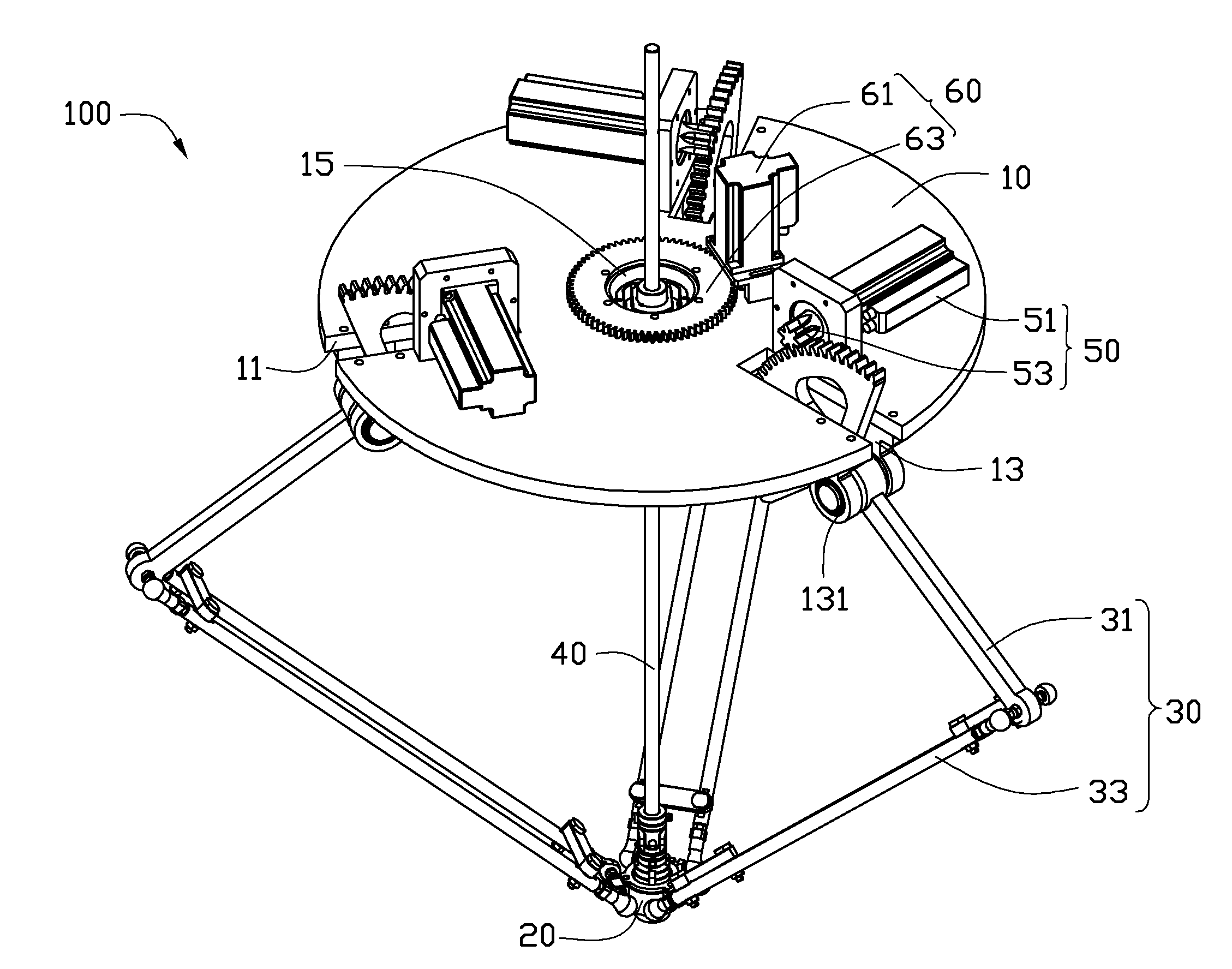
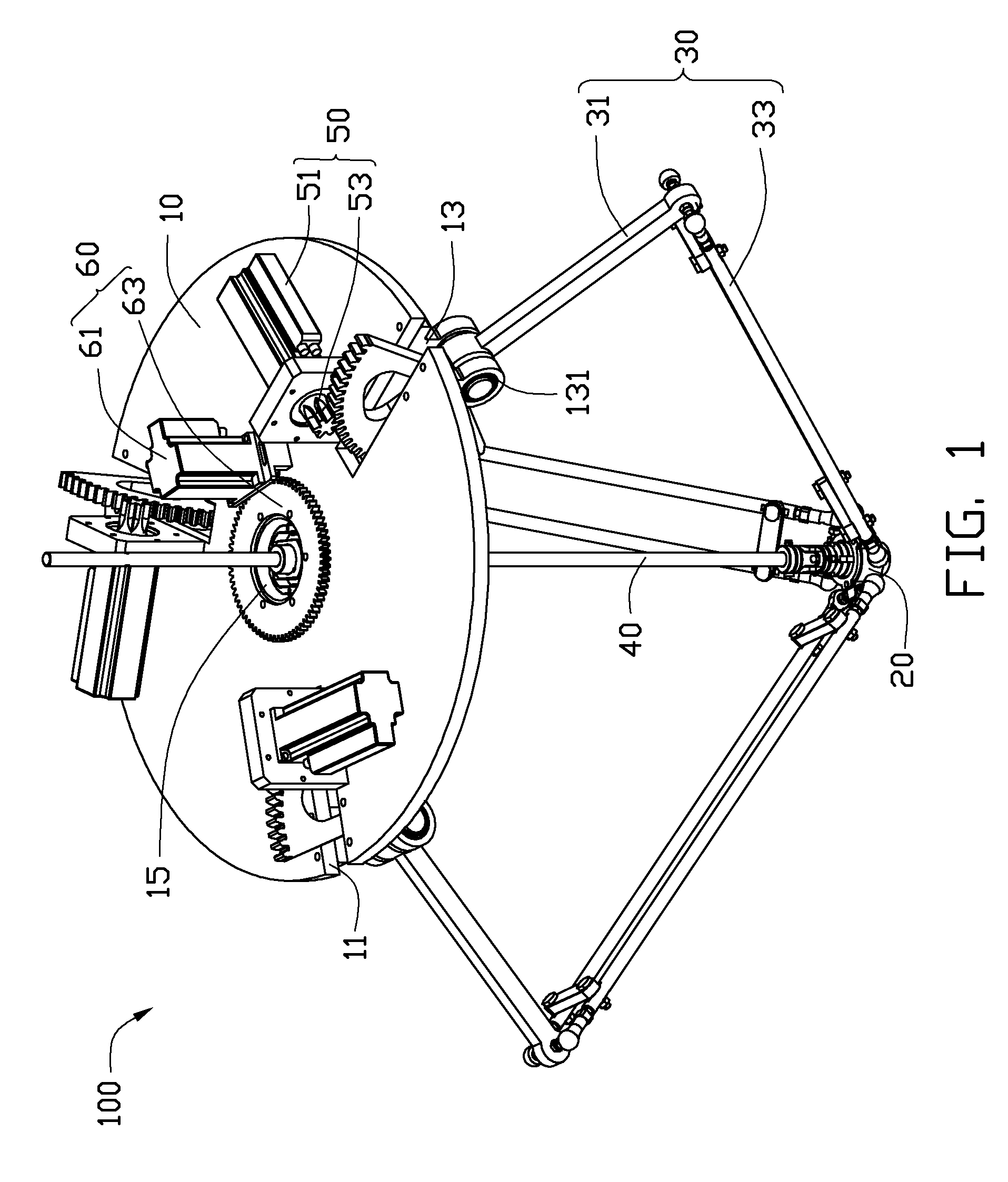
[0012]Referring to FIG. 1, an embodiment of a parallel robot 100 is shown. The parallel robot 100 includes a fixed platform 10, a movable platform 20, three control arms 30 rotatably connecting the fixed platform 10 to the movable platform 20, and a rotation arm 40. The parallel robot 100 further includes three first actuators 50 and a second actuator 60 mounted on the fixed platform 10.

[0013]The fixed platform 10 can be substantially circular-shaped. The fixed platform 10 defines three cutouts 11 at a periphery thereof and a mounting hole 15 in a center thereof. The cutouts 11 may be symmetrically arranged. The fixed platform 10 includes three connecting portions 13 formed adjacent to the cutouts 11. Each connecting portion 13 includes a support bearing 131.

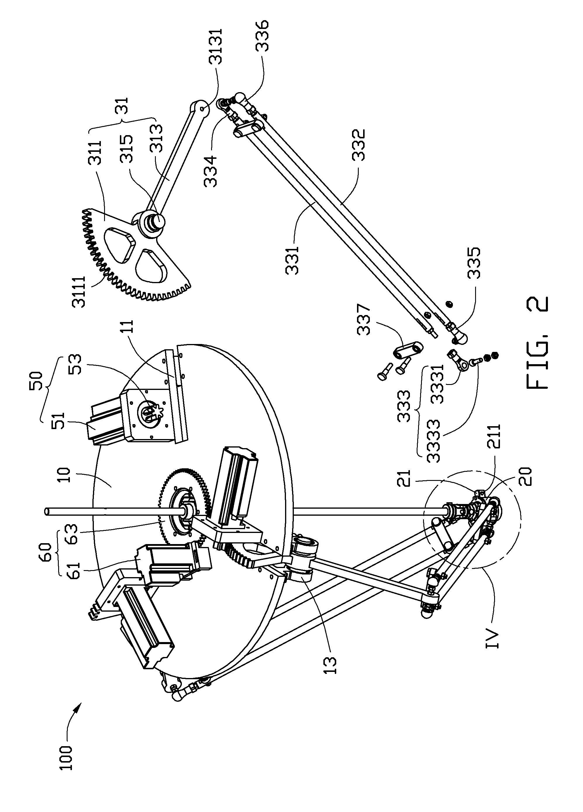
[0014]Referring to FIG. 1 and FIG. 2, the movable platform 20 includes three connecting portions 21 each defining a connecting hole 211.

[0015]Each control arm includes a first transmission unit 31 and a second transmission unit ...


PUM


Abstract

A parallel robot includes a fixed platform, a movable platform, a plurality of control arms, a rotation arm, a plurality of first actuators, and a second actuator. The control arms are rotatably connected to the fixed platform and the movable platform, respectively. Opposite ends of the rotation arm are universally rotatably connected to the fixed platform and the movable platform, respectively. The first actuators are to respectively move the control arms. The second actuator is to drive the rotation arm to rotate around the center axis of the rotation arm. Each control arm includes a first transmission unit including a transmission member. Each first actuator includes a transmission gear to engage the transmission member of the control arm.

Description

BACKGROUND[0001]1. Technical Field[0002]The present disclosure generally relates to parallel robots, and particularly, to a parallel robot having a simplified structure.[0003]2. Description of Related Art[0004]Parallel robots have advantages of stability, load-bearing, favorable weight to load ratio, and dynamic characteristics among other things. As parallel robots and series robots cooperate, they may be used in many fields.[0005]Some parallel robots include a fixed platform (also known as a base), a movable platform, a shaft, and three control arms. The shaft and the control arms connect the movable platform to the fixed platform. Each control arm includes an actuator mounted on the fixed platform, a first linking bar hinged to the movable platform, and a second linking bar hinged between the actuator and the first linking bar. The actuator includes a servo motor and a decelerator. The decelerator connects the servo motor and the first linking bar to adjust a rotation speed of th...

Claims


Application Information

Patent Timeline
IPC IPC(8): B25J18/00
CPCY10T74/20305B25J17/0266B25J9/0051
Inventor ZHANG, GUO-QINGZHAO, ZHI-MINGFENG, YONG
Owner HONG FU JIN PRECISION IND (SHENZHEN) CO LTD
Why Eureka
Try Eureka