Distance indicator

a technology of distance indicator and distance indicator, which is applied in the direction of instruments, signs, cleaning using liquids, etc., can solve the problems of complex or space-consuming, inaccurate devices used to indicate distances

Inactive Publication Date: 2011-05-19
BRIGGS & STRATTON
View PDF22 Cites 1 Cited by
  • Summary
  • Abstract
  • Description
  • Claims
  • Application Information

AI Technical Summary

Problems solved by technology

Devices used to indicate distances are oft

Method used


Image

  • Distance indicator
  • Distance indicator
  • Distance indicator

Examples


Embodiment Construction

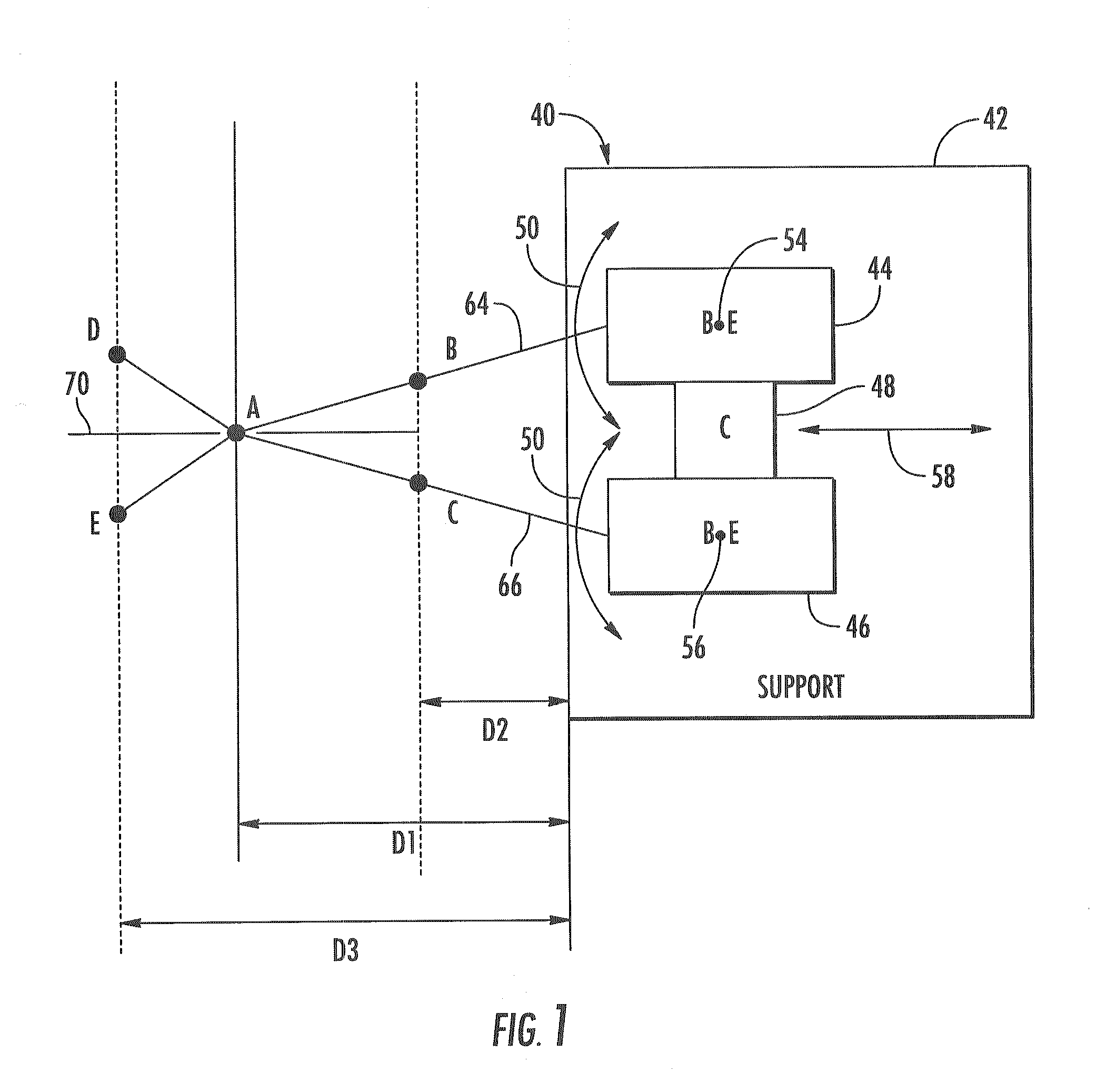
FIG. 1 schematically illustrates a distance indicator 40 according to an example embodiment. As will be described hereafter, distance indicator 40 indicates a distance in a relatively accurate, efficient and compact manner. Distance indicator 40 includes support 42, beam emitter 44, beam emitter 46 and coupling 48.

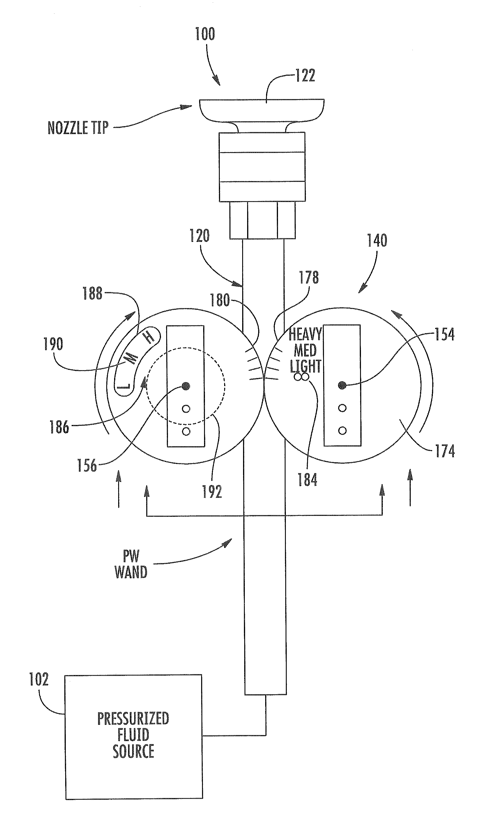
Support 42 comprises one or more structures configured to support or serve as a base or foundation for beam emitters 44, 46 and coupling 48. In one embodiment, support 42 comprises a base configured to be removably coupled to a device for which distance indication may be beneficial. For example, in one embodiment, support 42 may be configured to be removably coupled to a source of pressurized fluid having a spray gun that receives the pressurized fluid and directs emission of the pressurized fluid. In such an embodiment, distance indicator 40 provides the user with an indication of the distance separating the emission point of the spray gun and the target surface being imp...


PUM


Abstract

A method and apparatus utilize a first beam emitter and a second beam emitter coupled to the first beam emitter. The first beam emitter and the second beam emitter move in unison between a plurality of positions to indicate a plurality of distances separating the first beam emitter and the second beam emitter from endpoints of beams emitted by the first beam emitter and the second beam emitter.

Description

BACKGROUNDDevices used to indicate distances are often inaccurate, complex or space consuming.BRIEF DESCRIPTION OF THE DRAWINGSFIG. 1 is a schematic illustration of a distance indicator in a first state according to an example embodiment.FIGS. 2A-2C illustrates beam endpoints from coplanar beam emitters of the distance indicator upon a target surface when the distance indicator is at different distances from the target surface.FIG. 3 is a schematic illustration of the distance indicator of Figure in a second state according to an example embodiment.FIGS. 4A-4C illustrates beam endpoints from offset beam emitters of the distance indicator upon a vertical target surface when the distance indicator is at different distances from the target surface.FIGS. 5A-5C illustrates beam endpoints from offset beam emitters of the distance indicator upon a horizontal target surface when the distance indicator is at different distances from the target surface.FIG. 6 is a top plan view of a fluid spr...

Claims


Application Information

Patent Timeline
IPC IPC(8): B08B7/04B08B13/00B08B3/02G08B5/00
CPCB08B3/024
Inventor GILPATRICK, RICHARD J.CROUCH, STEVEN C.
Owner BRIGGS & STRATTON
Why Eureka
Try Eureka