Heat exchanger of upward combustion type condensing boiler

a condensing boiler and heat exchanger technology, applied in water heaters, climate sustainability, sustainable buildings, etc., can solve the problems of inability to reverse combustion, difficult combustion control, and long flames, so as to reduce the size of the entire boiler and maximize the latent heat recovery efficiency. , the effect of reducing the size of the latent heat exchange uni

Inactive Publication Date: 2011-05-19
VARIAN SEMICON EQUIP ASSOC INC +1
View PDF10 Cites 8 Cited by
  • Summary
  • Abstract
  • Description
  • Claims
  • Application Information

AI Technical Summary

Benefits of technology

[0037]According to the present invention, as the flow direction of exhaust gas in the latent heat exchange unit is caused to coincide with the falling direction of condensed water, it is possible to maximize latent heat recovery efficiency. Further, as the same fin-tube type heat exchanger is applied to the sensible heat exchange unit and the latent heat exchange unit, the sensible heat exchange unit does not need to be separately manufactured. Further, since the size of the latent heat exchange unit can be reduced, the size of the entire boiler can be reduced. Furthermore, although the condensed-water discharge port is clogged with condensed water, the condensed water can be prevented from falling to the sensible heat exchange unit, which makes it possible to safely stop an operation without a separate device.

Problems solved by technology

However, since the flames are formed by the secondary air, the flames lengthen, and downward combustion is impossible.
However, since a predetermined amount of air required for combustion should be premixed, combustion control is very complicated.
Further, since the premixed burner is easily affected by disturbance, its combustion stability is low.
However, the premixed burner has low combustion stability, and an expensive control system should be used to implement complicated combustion control.
However, the condensation efficiency of the upward combustion type condensing boiler is reduced by as much as 3-5%, compared with that of a traditional downward combustion type condensing boiler.
Therefore, since latent heat recovered by the condensation is discharged in the form of evaporation heat, it is impossible to obtain the maximum condensation efficiency.
However, it has only a limited effect.
This inevitably occurs, because the falling direction of the condensed water is set perpendicular to the flow direction of the exhaust gas.
As a result, a great part of the latent heat exchange unit 24 does not reliably carry out its primary function of condensation recovery.
There are difficulties in applying a fin-tube type heat exchanger (refer to FIG. 3), which is generally used as a sensible heat exchange unit, to the conventional upward combustion type condensing boiler.
Then, since a pressure loss of the exhaust gas excessively increases, the application is impossible in practice.
However, when the condensed-water discharge hose is bent or frozen such as in the winter, the condensed water is not discharged smoothly.
Therefore, the structure of the condensing boiler becomes complex, and the manufacturing cost increases.

Method used


Image

  • Heat exchanger of upward combustion type condensing boiler
  • Heat exchanger of upward combustion type condensing boiler
  • Heat exchanger of upward combustion type condensing boiler

Examples


Embodiment Construction

[0042]Hereinafter, example embodiments of the present invention will be described in detail with reference to the accompanying drawings.

[0043]FIG. 4 is a schematic view of an upward combustion type condensing boiler according to an example embodiment of the present invention.

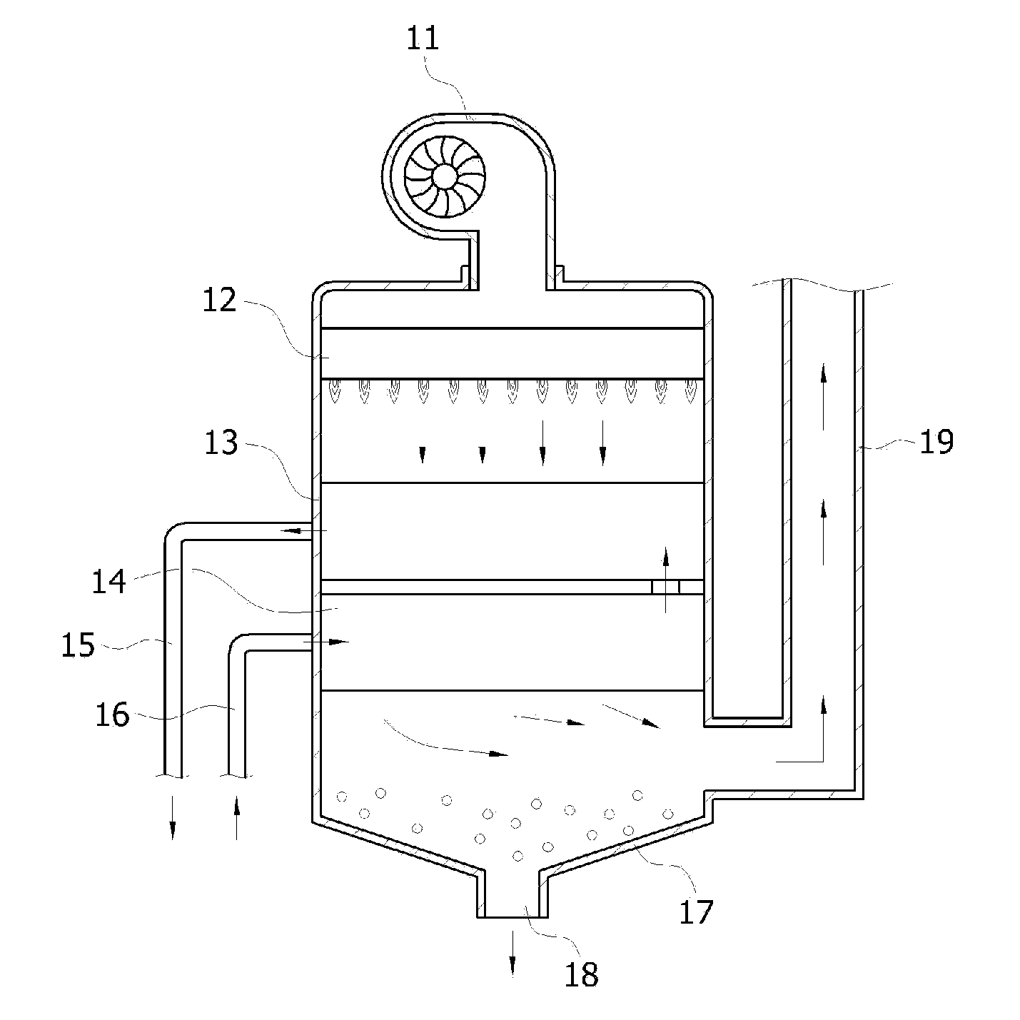
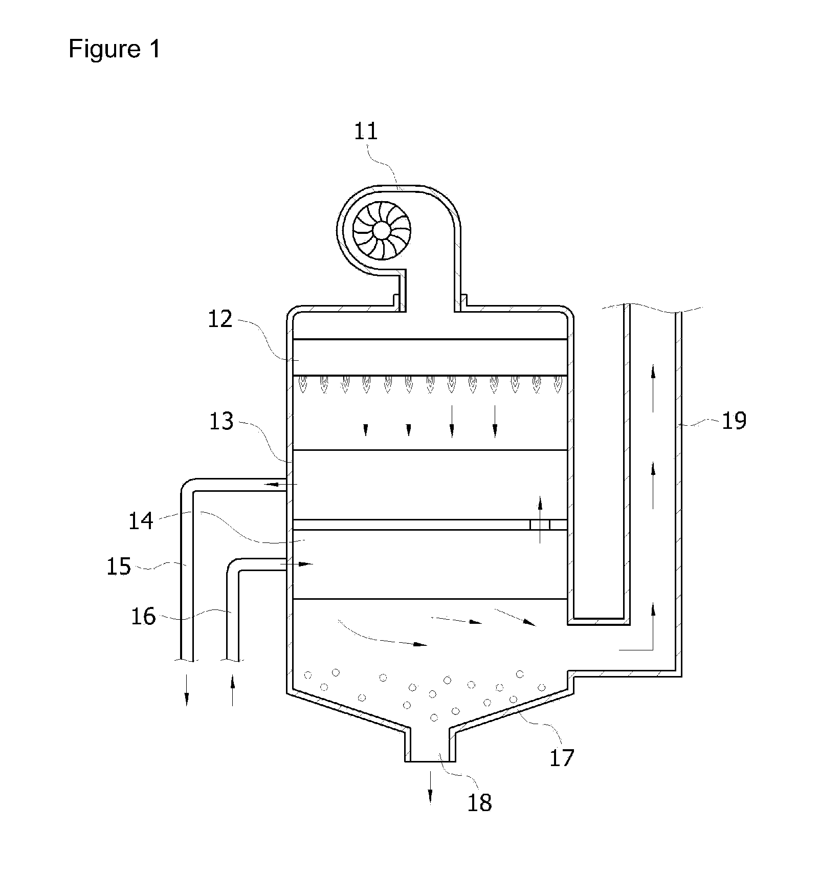
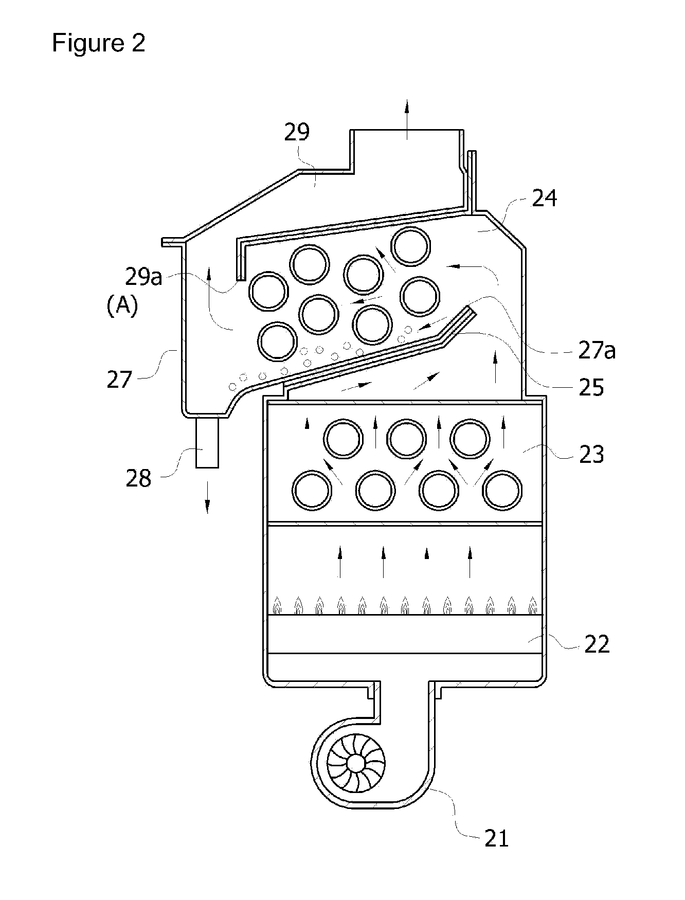
[0044]The condensing boiler according to the present invention includes an upward combustion type burner 120 which is installed directly above a blower 110 so as to form flames upward, a sensible heat exchange unit 130 which absorbs sensible heat generated from the burner 120, and a latent heat exchange unit 150 which absorbs latent heat of vapor included in exhaust gas which has been heat-exchanged in the sensible heat exchange unit 130.

[0045]For the burner 120, any one of a Bunsen burner and a premixed burner may be used. The Bunsen burner supplies the minimum primary air, which is required for combustion, to a nozzle unit, and supplies secondary air to a portion where flames are formed. The premixed burner pr...


PUM


Abstract

A heat exchanger of an upward combustion condensing boiler maximizes latent-heat recovery efficiency by causing the flow direction of exhaust gas to coincide with the flow direction of condensed water in a latent heat exchange unit. The heat exchanger includes a sensible heat exchange unit that absorbs sensible heat generated from an upward combustion burner; a latent heat exchange unit that absorbs latent heat of vapor included in exhaust gas which has been heat-exchanged in the sensible heat exchange unit; and a condensed-water tray that discharges condensed water generated from the latent heat exchange unit. An upward flow of exhaust gas passed through the sensible heat exchange unit is converted into a downward flow that passes through the latent heat exchange unit, and the latent heat exchange unit is installed so that the flow direction of the exhaust gas passing through the latent heat exchange unit vertically coincides with the falling direction of condensed water generated by the latent heat exchange unit.

Description

TECHNICAL FIELD[0001]The present invention relates to a heat exchanger of an upward combustion type condensing boiler, and more specifically, to an upward combustion type condensing boiler in which a sensible heat exchanger and a latent heat exchanger are sequentially disposed above an upward combustion type burner.BACKGROUND ART[0002]Boilers currently produced are boilers including a heat exchanger to increase heat efficiency. Such a heat exchanger is composed of a sensible heat exchange unit and a latent heat exchange unit. The sensible heat exchange unit absorbs sensible heat of exhaust gas generated from a combustion chamber, and the latent heat exchange unit absorbs residual heat and latent heat from the exhaust gas which has been heat-exchanged in the sensible heat exchange unit. Such a type of boiler is referred to as a condensing boiler.[0003]Such condensing boilers have been put to practical use as oil boilers which use oil fuel as well as gas boilers which use gas fuel suc...

Claims


Application Information

Patent Timeline
Patent Type & Authority Applications(United States)
IPC IPC(8): F28F1/12
CPCF24H1/40F24H8/00Y02B30/106Y02B30/102F24H8/006Y02B30/00F24H1/445F24H9/0031F24H9/1836F24H9/13
Inventor KIM, YONG-BUMMIN, MYOUNG-GEE
Owner VARIAN SEMICON EQUIP ASSOC INC
Why Eureka
Try Eureka