Thermal electric power generator

a technology of electric power generators and generators, applied in the direction of machines/engines, mechanical equipment, light and heating equipment, etc., can solve the problem of forcing the stop of waste heat power generators, etc., and achieve the effect of stopping safely

Active Publication Date: 2016-06-30
PANASONIC INTELLECTUAL PROPERTY MANAGEMENT CO LTD
View PDF8 Cites 5 Cited by
  • Summary
  • Abstract
  • Description
  • Claims
  • Application Information

AI Technical Summary

Benefits of technology

[0011]The above-described technique enables the thermal electric power generator to stop safely by using the bypass channel and the flow rate adjustment mechanism in the event of a failure of the thermal electric power generator.

Problems solved by technology

The waste heat power generator is forced to be stopped in an emergency situation due to a malfunction in some cases.

Method used


Image

  • Thermal electric power generator
  • Thermal electric power generator
  • Thermal electric power generator

Examples


first embodiment

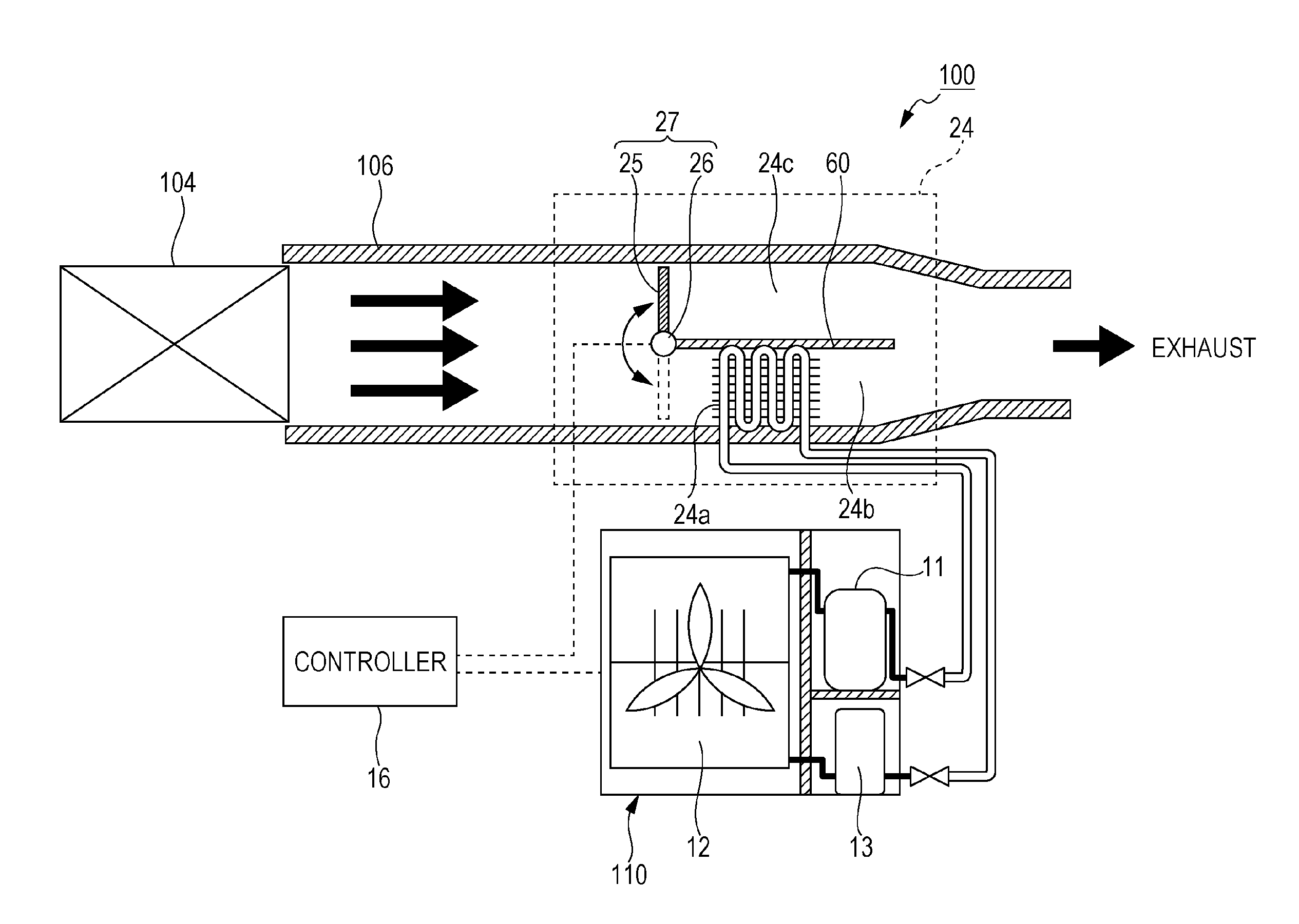
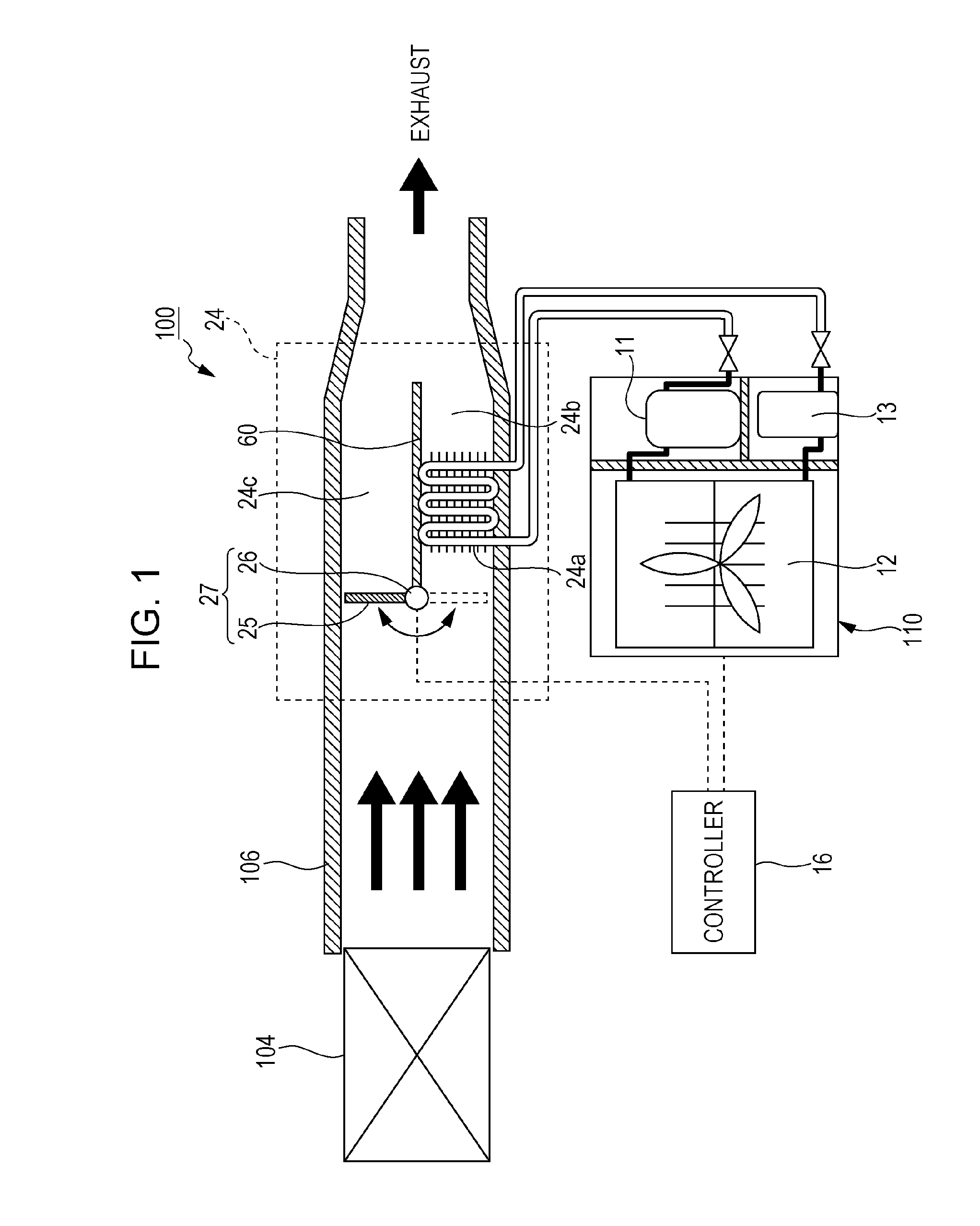
[0052]As illustrated in FIG. 1, a thermal electric power generator 100 includes an evaporator 24, an expander 11, a condenser 12, a pump 13, and a controller 16. The evaporator 24, the expander 11, the condenser 12, and the pump 13 are connected in this sequence in a loop through pipes to form a rankine cycle circuit. A heat medium having a high temperature is supplied from a heat source 104 to the thermal electric power generator 100 through a duct 106. The thermal electric power generator 100 generates electric power by using the high-temperature heat medium generated by the heat source 104.

[0053]Kinds of the heat source 104 are not limited. Kinds of the heat medium supplied from the heat source 104 to the thermal electric power generator 100 are also not limited. The heat medium having a high temperature of 100 to 500° C., for example, is generated by the heat source 104. The heat source 104 may be a furnace such as a waste incinerator, a combustion furnace, or a firing furnace, ...

first modification

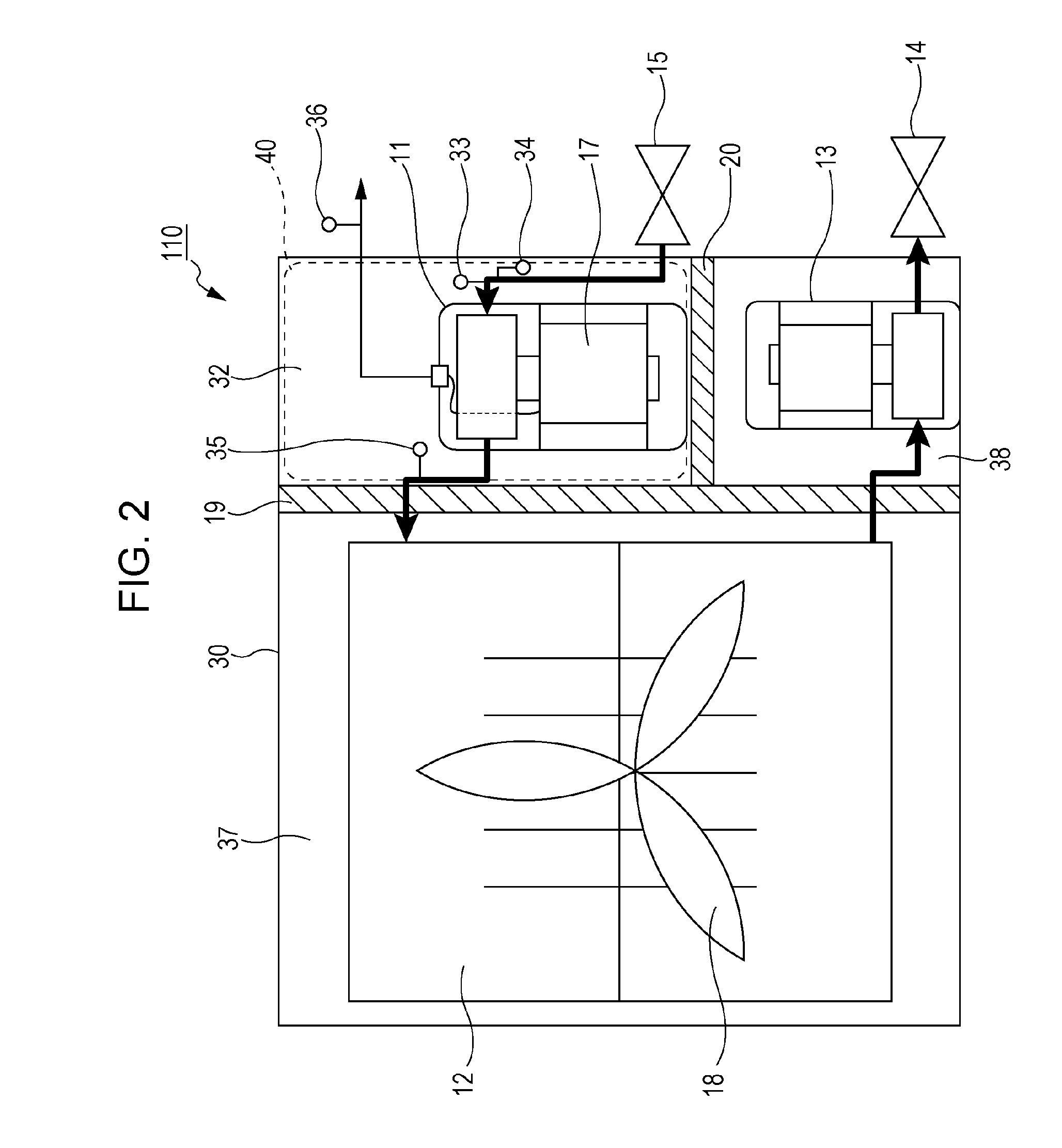
[0084]As illustrated in FIG. 3, an air cooling unit 112 of a first modification further includes a reheater 21, an expander bypass channel 22, and a valve 23 in addition to the components of the air cooling unit 110 described with reference to FIG. 2. The reheater 21, the expander bypass channel 22, and the valve 23 are disposed in the casing 30. The expander bypass channel 22 extends so as to allow the working fluid to bypass the expander 11. Specifically, the expander bypass channel 22 extends so as to connect a channel 50, through which the working fluid flows to the expander 11, and a channel 52, through which the working fluid expelled from the expander 11 flows, to each other at an outside of the expander 11 to bypass the expander 11. The expander bypass channel 22 allows the working fluid to flow into the reheater 21 without flowing through the expander 11. If the air cooling unit 112 does not include the reheater 21, the working fluid may be supplied to the condenser 12 thro...

second modification

[0094]As illustrated in FIG. 4, an air cooing unit 114 of this modification includes an additional expander bypass channel 29 and a second valve 28 in addition to the components of the air cooling unit 112 in the first modification. The additional expander bypass channel 29 extends in parallel with the expander bypass channel 22 and allows the working fluid to flow into the reheater 21 without passing through the expander 11. The second valve 28 may be a relief valve. Specifically, if a difference between the pressure at the inlet of the expander 11 and the pressure at the outlet of the expander 11 exceeds a threshold, i.e., if a failure occurs in the thermal electric power generator 100, the second valve 28 opens. This configuration reduces an increase in pressure inside the thermal electric power generator 100 in the event of a failure of the thermal electric power generator 100. The second valve 28 functions as a safety valve that mechanically opens or closes depending on a prede...


PUM


Abstract

A thermal electric power generator includes an evaporator, an expander, an electric generator, a condenser, and a pump. A working fluid used in the thermal electric power generator is an organic working fluid. The evaporator includes a heat exchanger, a bypass channel, and a flow rate adjustment mechanism. The bypass channel allows a heat medium to bypass the heat exchanger. The flow rate adjustment mechanism adjusts a flow rate of the heat medium to be supplied to the heat exchanger and a flow rate of the heat medium to be supplied to the bypass channel.

Description

BACKGROUND[0001]1. Technical Field[0002]The present disclosure relates to a thermal electric power generator.[0003]2. Description of the Related Art[0004]As is well known to those skilled in the art, the rankine cycle is a theoretical cycle for steam turbines. The rankine cycle has been studied and developed for a long time. A waste heat power generator has also been studied and developed as described in Japanese Unexamined Patent Application Publication No. 2013-7370. The waste heat power generator recovers waste heat energy released from a facility such as a plant or a firing furnace to generate electric power.[0005]In the waste heat power generator described in Japanese Unexamined Patent Application Publication No. 2013-7370, an evaporator recovers thermal energy from a waste heat medium, and the recovered thermal energy evaporates a working fluid in the rankine cycle. The evaporated working fluid activates a turbine electric generator. The working fluid that has activated the tu...

Claims


Application Information

Patent Timeline
Patent Type & Authority Applications(United States)
IPC IPC(8): F01K19/00H02K7/18F01K13/00F01K25/08F01K9/00
CPCF01K19/00F01K25/08H02K7/18F01K13/003F01K9/003F01K13/02F22B1/167F22B37/42Y02E20/12
Inventor MATSUMOTO, SUBARUKIDO, OSAOOKAICHI, ATSUOHIKICHI, TAKUMIKOSUDA, OSAMUNISHIYAMA, NORIYOSHI
Owner PANASONIC INTELLECTUAL PROPERTY MANAGEMENT CO LTD
Why Eureka
Try Eureka