Drive unit, belt unit, bridge, driver and stamp therefor

Active Publication Date: 2019-10-03
TRODAT GMBH
View PDF0 Cites 6 Cited by
  • Summary
  • Abstract
  • Description
  • Claims
  • Application Information

AI Technical Summary

Benefits of technology

[0025]Here, too, it is advantageous that the very thin formation of the soft layer, i.e. the outer component of the 2C driver, ensures that no deformations can occur, but that the high frictional properties for the safe further transport of a band are present. Due to the possibility of 2C manufacture, optimal adaptation of the materials to each other can be possible, i.e. the drive wheel, in particular the driver, is produced with an external component that has a very high frictional locking connection with the material of the band, so that slippage during turning is prevented.
[0026]F

Problems solved by technology

A disadvantage of the aforementioned prior art is that the rubber pads on the driver brought about significant improvements for a short period of time, but had significant disadvantages in long-term operation, so that the stamp-making industry preferably uses one-part plastic adjustment wheels with drivers made of hard, non-elastic plastic materials.
In order to ensure reliable transport of the band, however, some manufacturers use special surfaces, especially with grooves or projections, on the driver, wherein the conveyor band is designed correspondingly here, resulting in more complicated production of the systems.
For with the systems from the prior art with correspondingly plugged-on

Method used


Image

  • Drive unit, belt unit, bridge, driver and stamp therefor
  • Drive unit, belt unit, bridge, driver and stamp therefor
  • Drive unit, belt unit, bridge, driver and stamp therefor

Examples


Embodiment Construction

[0046]It should be stated by way of introduction that, in the individual embodiments, the same parts are provided with the same reference numbers or same component designations, respectively, wherein the disclosures contained in the entire description can, by analogy, be transferred mutatis mutandis to identical parts with identical reference numbers or identical component designations, respectively. The position details selected in the description, such as, e.g., top, bottom, lateral, etc., relate to the figure described, and in the event of a change of position, they are to be transferred to the new position by analogy. Individual features or feature combinations from the exemplary embodiments shown and described may also represent independent inventive solutions.

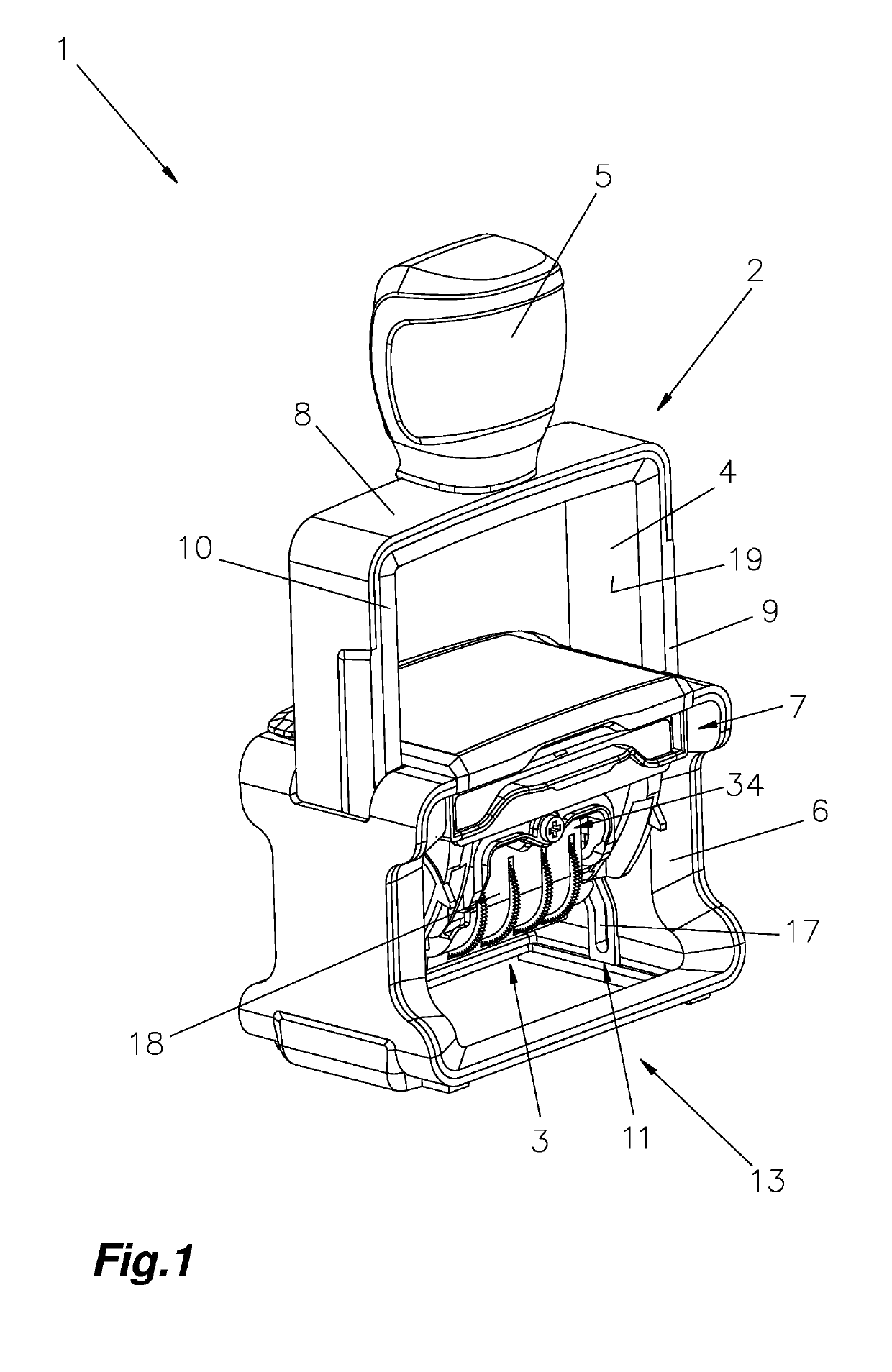
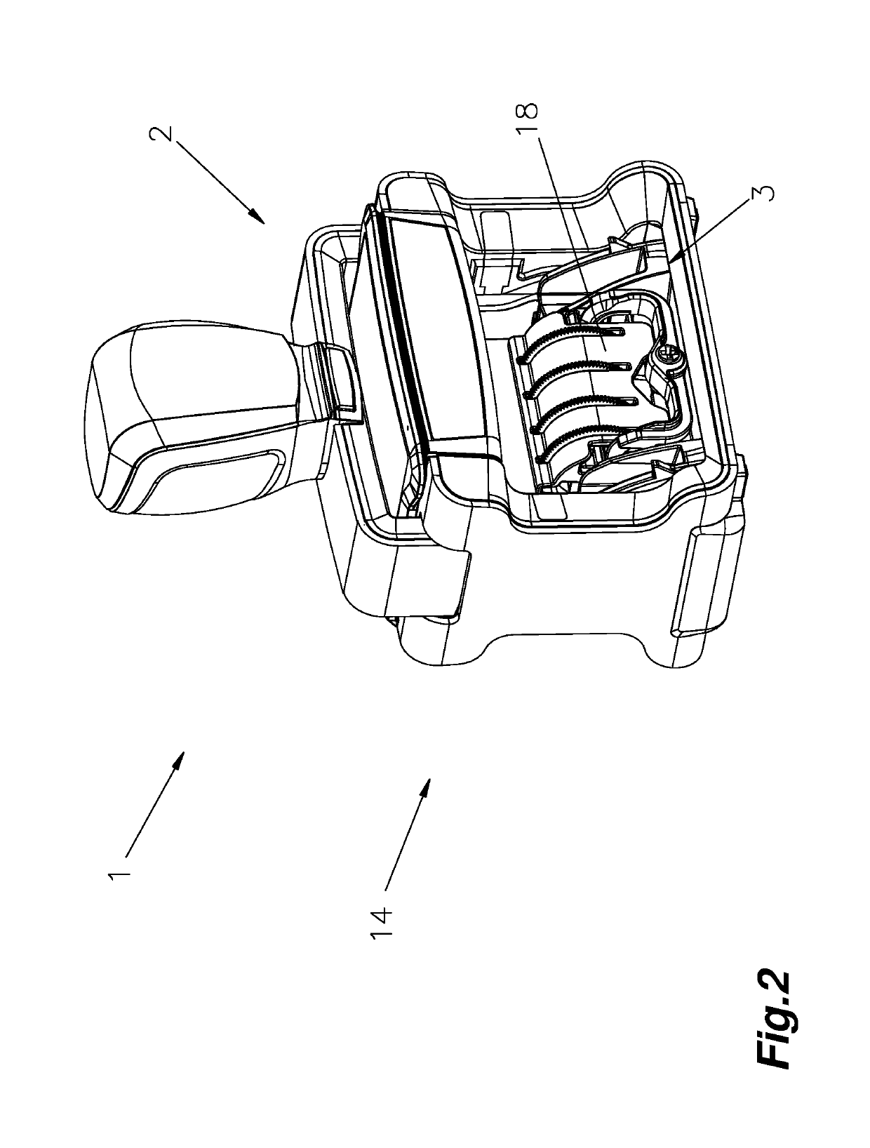
[0047]In FIGS. 1 and 2, an exemplary embodiment of a stamp 1, in particular a self-inking stamp 1, is shown, comprising at least a stamping component 2 and one impression unit 3.

[0048]The stamping component 2 consists at ...


PUM


Abstract

In some embodiments, a system includes a stamp, a band gear, a bridge, a driver, and a drive unit, in particular an ABU, preferably for a band gear in an impression unit for a stamp (1). The system includes at least an adjustment wheel with a driver, and a so-called bridge. A band is fastened over the driver and around the bridge. When the adjustment wheel is actuated, the band is adjusted via the driver. The driver of the band gear is formed from at least two different materials, in particular a 2C injection-moulded component. The outer component butting against the band or conveyor band, respectively, has a low thickness preferably of less than 1.5 mm, in particular 0.4 to 0.8 mm.

Description

BACKGROUND OF THE INVENTIONField of the Invention[0001]The present disclosure relates to an improved drive unit for a stamp including an impression unit.2. Description of the Relevant Art[0002]DE 16 54 769 U discloses a drive unit in which the band gear consists of an adjustment wheel and a driver for the conveyor band, wherein the adjustment wheel and the driver are formed from one piece. In addition, a rubber pad is provided on the driver, which is intended to improve the transport of the conveyor band.[0003]In addition, DE 17 96 254 U discloses a drive unit, in which a soft rubber or rubber-like plastic is plugged onto the driver. This friction lining has a surface with a knobbed profile. The knobbed profile is intended to ensure that a corresponding deformation occurs, and that thus reliable transport of the band is ensured.[0004]WO 2006 / 079129 A1 discloses a type unit, in which the adjustment wheel is formed from a 2C injection-moulded component. This is intended to improve ope...

Claims


Application Information

Patent Timeline
IPC IPC(8): B41K1/10B41K1/40
CPCB41K1/40B41K1/10B41K1/36
Inventor LEIBEZEDER, REINHARDRIEGLER, KONRADLINDNER, HELMUT
Owner TRODAT GMBH
Why Eureka
Try Eureka