Microwave oven and related method

a microwave oven and microwave technology, applied in dielectric heating circuits, sustainable buildings, electric/magnetic/electromagnetic heating, etc., can solve the problems of severe limitations in the available output power per unit of money, and the cost per watt of output microwave power is still high for ssmgs compared to traditional magnetrons, so as to improve resolution and predictability.

Active Publication Date: 2011-05-19
WHIRLPOOL CORP
View PDF5 Cites 31 Cited by
  • Summary
  • Abstract
  • Description
  • Claims
  • Application Information

AI Technical Summary

Benefits of technology

[0008]It has now been recognized that the use of tunable signal sources, such as solid state microwave generators (SSMGs) can greatly improve the resolution and predictability when determining presence and / or nature of a load in the cavity of a microwave oven.

Problems solved by technology

However, SSMGs suffer from a major drawback in that the available output power per unit of money is severely limited compared to that obtainable from magnetrons.
Another way of expressing this drawback is that the cost per watt of output microwave power is still today high for SSMGs compared to traditional magnetrons.

Method used


Image

  • Microwave oven and related method
  • Microwave oven and related method
  • Microwave oven and related method

Examples


Embodiment Construction

[0051]While concepts of the present disclosure are susceptible to various modifications and alternative forms, specific exemplary embodiments thereof have been shown by way of example in the drawings and will herein be described in detail. The present disclosure may, however, be embodied in many different forms and should not be construed as limited to the embodiments set forth herein; rather, these embodiments are provided by way of example so that this disclosure will be thorough and convey the scope of the invention to those skilled in the art. The steps of any method disclosed herein do not have to be performed in the exact order disclosed, unless explicitly stated.

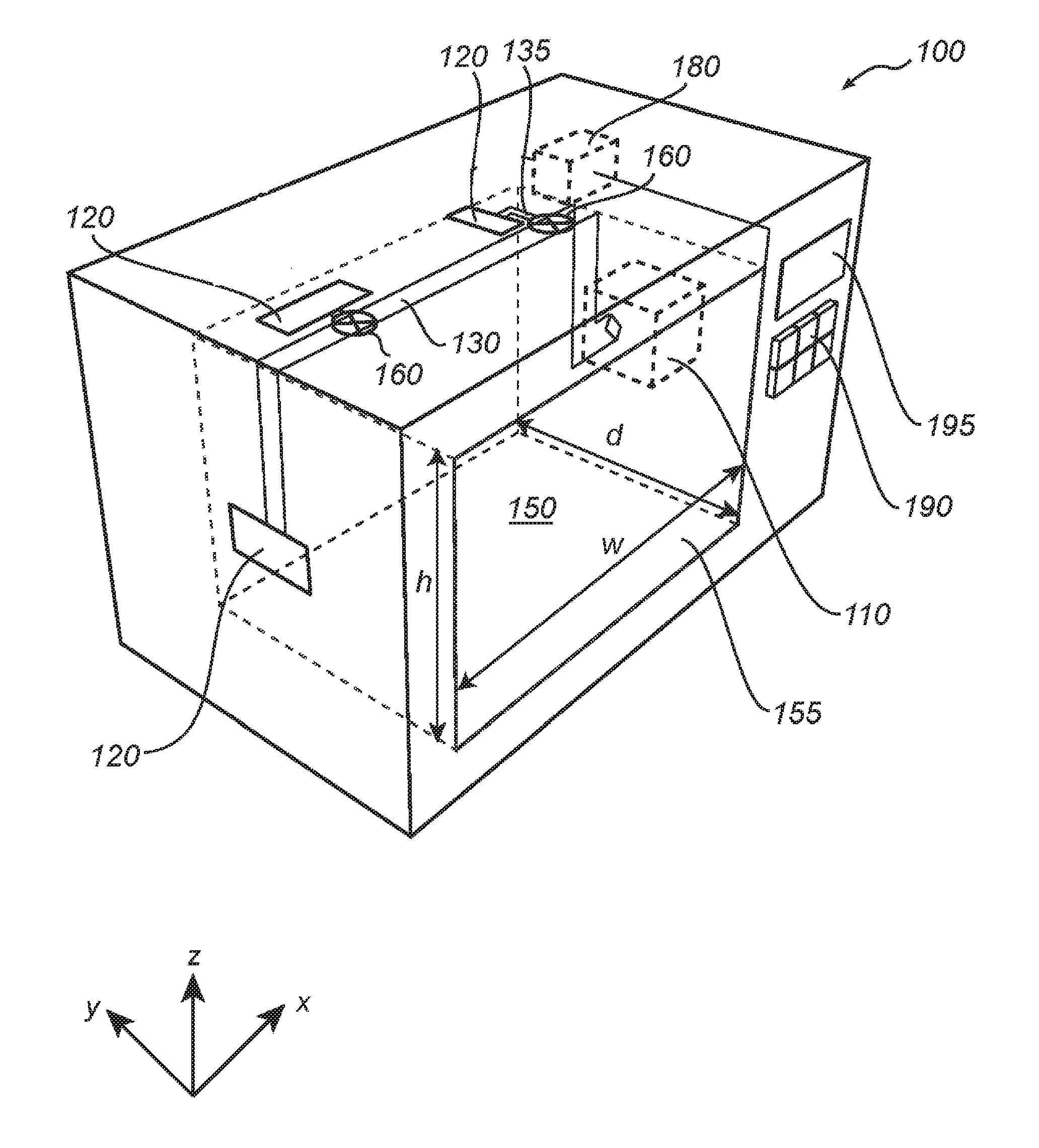
[0052]With reference to FIG. 1, there is shown a microwave oven 100 according to an exemplifying embodiment of the present disclosure.

[0053]The microwave oven 100 comprises a cavity 150 defined by an enclosing surface. One of the sides of the cavity 150 has an opening 155 for enabling the introduction of a load, e.g. ...


PUM


Abstract

A method of operating a microwave oven and a microwave oven are disclosed. The microwave oven comprises a magnetron for providing microwave power to heat a load placed in the microwave oven, and a solid-state microwave generator for providing microwave power to sense presence and/or determine nature of the load in the microwave oven.

Description

BACKGROUND OF THE INVENTION[0001]1. Field of the Invention[0002]The present invention relates to a microwave oven and a method of operating a microwave oven.[0003]2. Description of the Related Art[0004]A typical microwave oven includes a cavity for receiving a load to be heated. Microwave energy is generated by means of a magnetron, and the magnetron is operatively connected by a waveguide to feeding ports for feeding microwave energy into the cavity.[0005]Various efforts have previously been made to determine the presence and / or nature of a load placed in the cavity. One reason for determining the presence and / or nature of a load in the cavity is that strong reflection from the cavity typically occurs when the cavity is empty. Such reflection may deteriorate or even destroy the magnetron. For example, WO 03 / 07929 discloses a method in which a microwave signal escaping from an orifice placed in the wall of the cavity is measured, and the measured signal is used for determining prese...

Claims


Application Information

Patent Timeline
Patent Type & Authority Applications(United States)
IPC IPC(8): H05B6/50
CPCH05B6/686H05B6/705H05B6/688Y02B40/146Y02B40/143H05B6/6488Y02B40/00
Inventor NIKLASSON, OLLENORDH, ULF ERIHHALLGREN, FREDRIKCARLSSON, HAKAN
Owner WHIRLPOOL CORP
Why Eureka
Try Eureka