Display device and touch panel thereof

a technology of display device and touch panel, which is applied in the field of touch panel, can solve the problems of poor wearability of ito layer, uneven resistance over the entire area of the panel, and relatively complicated undertaking,

Inactive Publication Date: 2011-05-19
BEIJING FUNATE INNOVATION TECH
View PDF20 Cites 27 Cited by
  • Summary
  • Abstract
  • Description
  • Claims
  • Application Information

AI Technical Summary

Problems solved by technology

The ITO layer is generally formed by ion beam sputtering, a relatively complicated undertaking.
Furthermore, the ITO layer has poor wearability, low chemical endurance and uneven resistance over the entire area of the panel, as well as relatively low transparency.
Such characteristics of the ITO layer can significantly impair sensitivity, accuracy, and brightness.

Method used


Image

  • Display device and touch panel thereof
  • Display device and touch panel thereof
  • Display device and touch panel thereof

Examples


Embodiment Construction

[0014]The disclosure is illustrated by way of example and not by way of limitation in the figures of the accompanying drawings in which like references indicate similar elements. It should be noted that references to “an” or “one” embodiment in this disclosure are not necessarily to the same embodiment, and such references mean at least one.

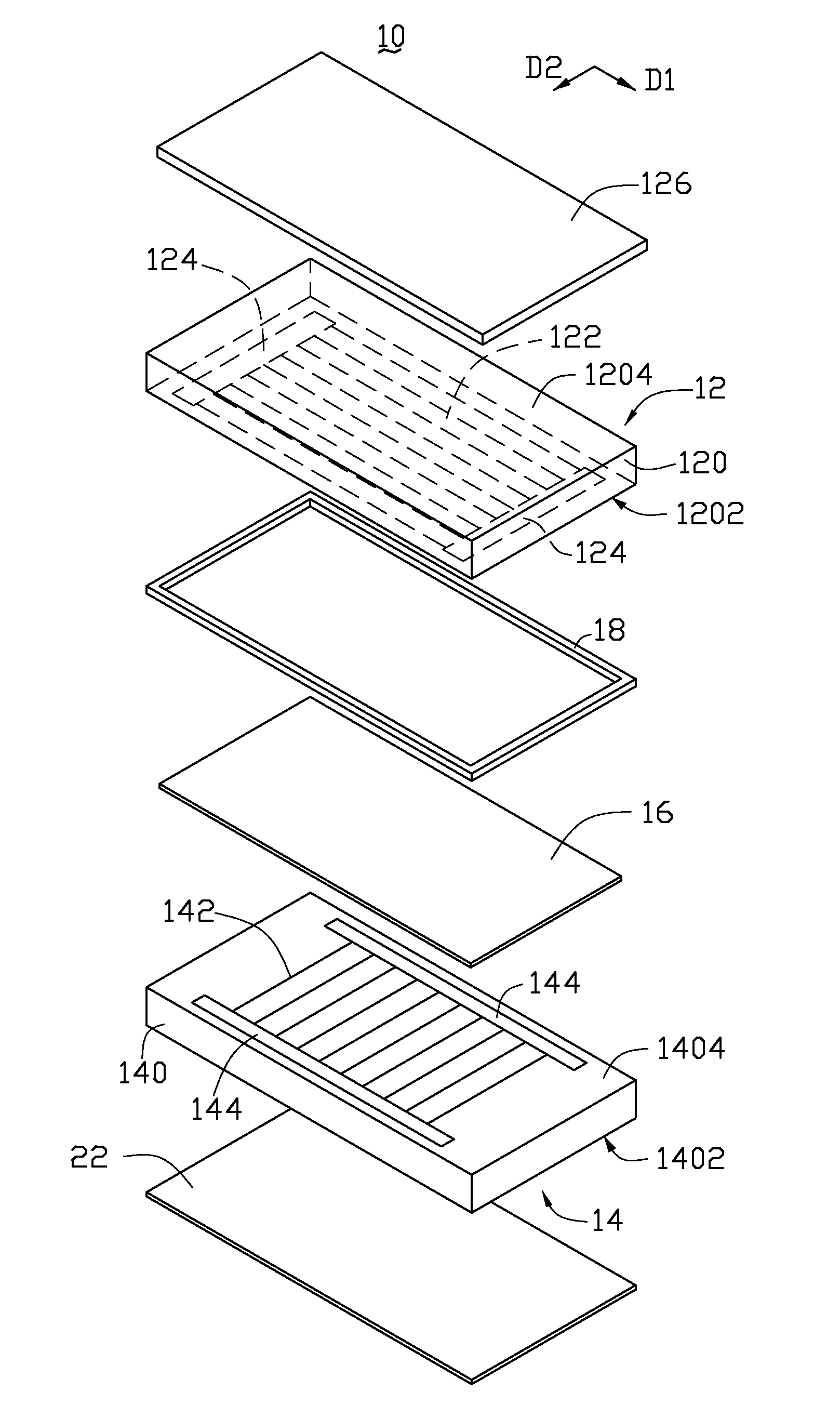
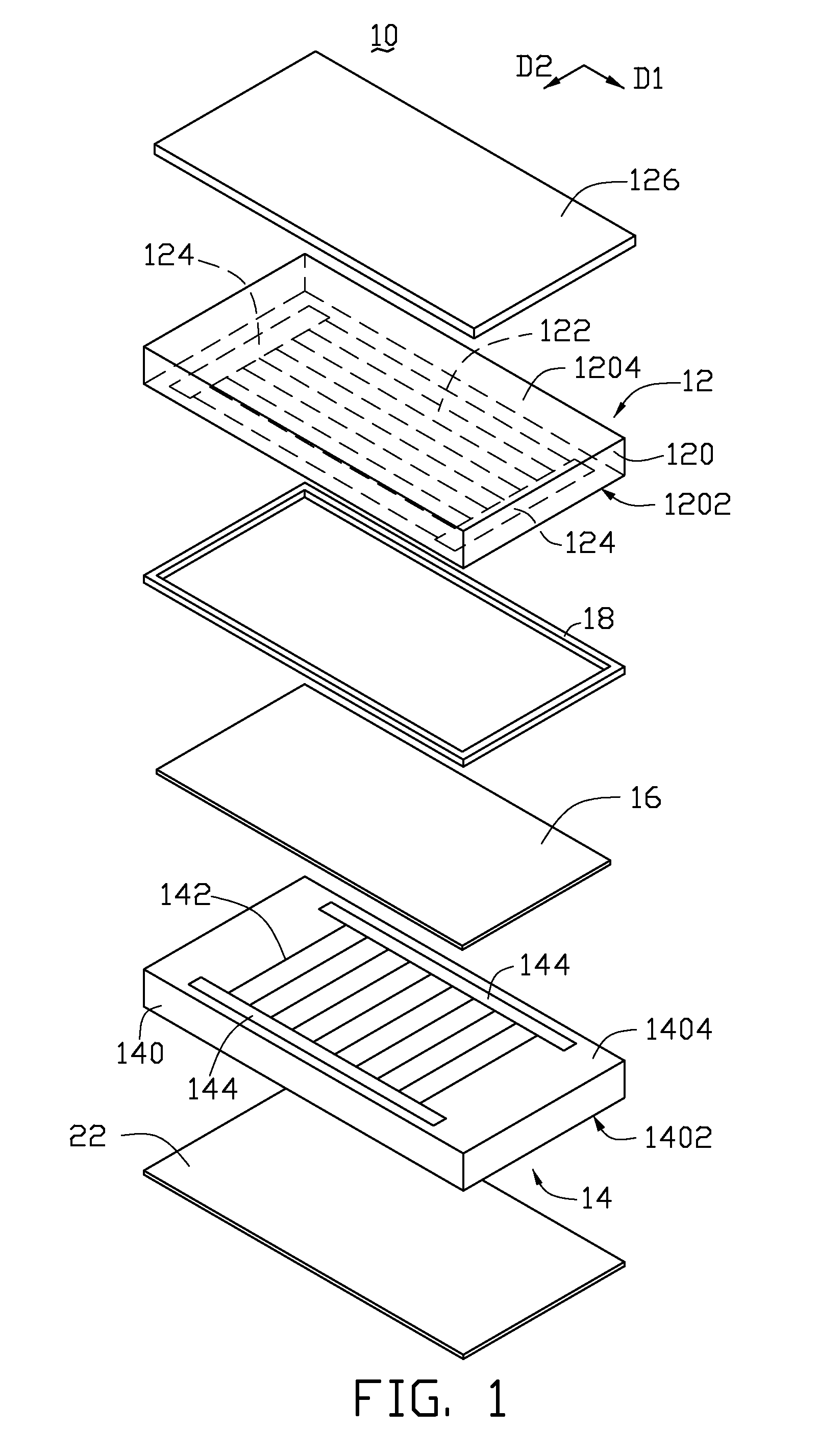
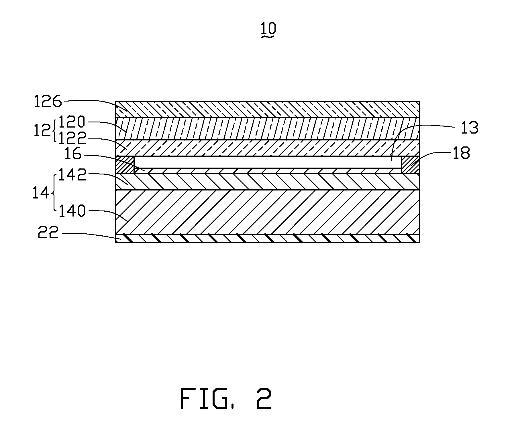
[0015]Referring to FIG. 1 and FIG. 2, one embodiment of a touch panel 10 comprises a first electrode plate 12, a second electrode plate 14, and a transparent insulating layer 16 located between the first electrode plate 12 and the second electrode plate 14.

[0016]The first electrode plate 12 includes a first substrate 120, a first conductive layer 122, and two first electrodes 124. The first substrate 120 includes a first surface 1202 and an opposite second surface 1204, each of which can be substantially flat. The first surface 1202 is opposite to and spaced from the second electrode plate 14. The first conductive layer 122 is adhered to the firs...


PUM


Abstract

A touch panel includes a first electrode plate, a second electrode plate, and a continuous transparent insulating layer. The first electrode plate includes a first conductive layer. The second electrode plate includes a second conductive layer opposite to and spaced from the first conductive layer. The continuous transparent insulating layer is located between the first conductive layer and the second conductive layer. At least one of first conductive layer and the second conductive layer includes a carbon nanotube structure.

Description

CROSS-REFERENCE TO RELATED APPLICATIONS[0001]This application claims all benefits accruing under 35 U.S.C. §119 from China Patent Application No. 200910223722.2, filed on 2009 / 11 / 18, in the China Intellectual Property Office, the disclosure of which is incorporated herein by reference.BACKGROUND[0002]1. Technical Field[0003]The disclosure relates to touch panels and, particularly, to a carbon nanotube-based touch panel and a display device incorporating the same.[0004]2. Description of Related Art[0005]Various electronic apparatuses such as mobile phones, car navigation systems and the like are equipped with optically transparent touch panels applied over display devices such as liquid crystal panels. The electronic apparatus is operated when contact is made with the touch panel corresponding to elements appearing on the display device. A demand thus exists for such touch panels to maximize visibility and reliability in operation.[0006]Resistive, capacitive, infrared, and surface ac...

Claims


Application Information

Patent Timeline
Patent Type & Authority Applications(United States)
IPC IPC(8): G06F3/041
CPCG06F3/0412G06F3/045G06F3/044G06F3/0447G06F3/0445
Inventor FENG, CHENQIAN, LI
Owner BEIJING FUNATE INNOVATION TECH
Why Eureka
Try Eureka