Coordinate locating method and apparatus

a technology of coordinate locating and apparatus, applied in the direction of measuring devices, instruments, using optical means, etc., can solve the problems of increased manufacturing costs, undesirably limited applications, and high manufacturing costs, and achieve the effect of reducing the complexity of calculation and costing less to manufactur

Active Publication Date: 2011-05-19
HONG KONG APPLIED SCI & TECH RES INST
View PDF33 Cites 13 Cited by
  • Summary
  • Abstract
  • Description
  • Claims
  • Application Information

AI Technical Summary

Benefits of technology

In view of above, a coordinate locating apparatus is provided which has the ability to locate the coordinates of two or more objects, costs less to manufacture than devices using conventional techniques, and reduces the complexity of calculation.

Problems solved by technology

Among these devices, those employing crossed light beams are not limited by the display panel size and are therefore cost competitive.
However, the apparatus can only locate the coordinates of one object, resulting in undesirably limited applications.
However, both require at least three image sensors, which greatly increases manufacturing costs.
However, the complexity of calculation increases with the number of touch points to be located.

Method used


Image

  • Coordinate locating method and apparatus
  • Coordinate locating method and apparatus
  • Coordinate locating method and apparatus

Examples


Embodiment Construction

.”

BRIEF DESCRIPTION OF THE DRAWINGS

Features, aspects, and embodiments are described in conjunction with the attached drawings, in which:

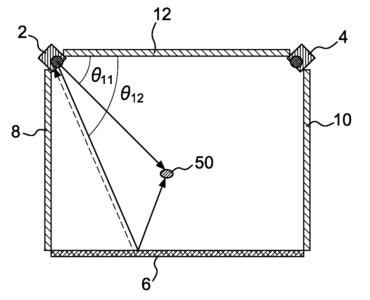
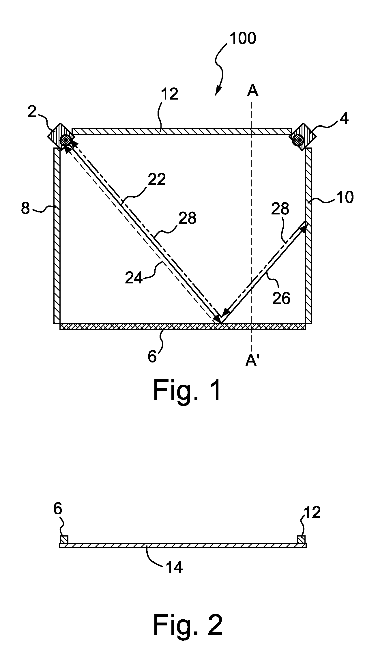
FIG. 1 is a schematic diagram showing the plane view of the structure of a coordinate locating apparatus in accordance with an embodiment;

FIG. 2 is the cross section view of the coordinate locating apparatus along line AA′ in FIG. 1;

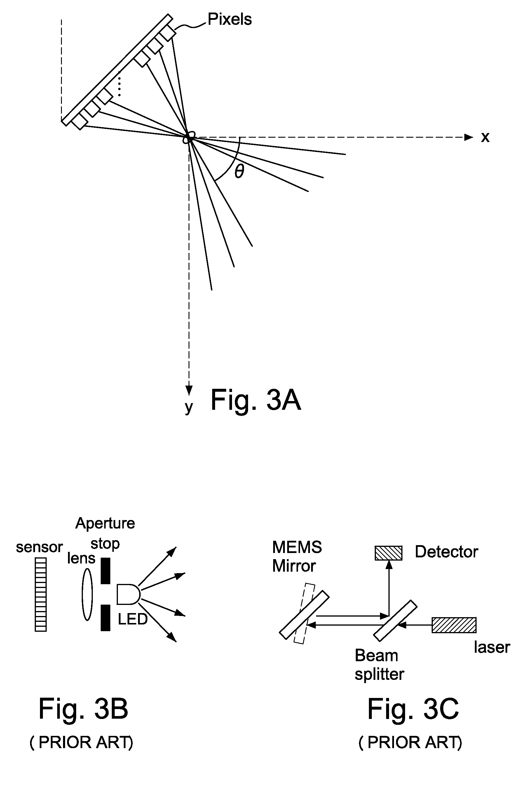
FIG. 3A is a diagram representing the relationship between pixel number and detection angle in the detecting unit implemented as an image sensor;

FIG. 3B is a schematic diagram of a conventional image sensor;

FIG. 3C is a schematic diagram of a conventional laser scanning unit;

FIG. 4 is a side view of the coordinate locating apparatus in a preferred embodiment;

FIG. 5A is a diagram illustrating the operation of the detecting unit when a touch point exists;

FIG. 5B is a diagram illustrating the signals generated by the receiving element of the detecting unit;

FIG. 6A is a diagram illustrating the operation of the coordinate lo...


PUM


Abstract

A coordinate locating apparatus for locating at least one touch point on a plane and the method thereof are provided. The coordinate locating apparatus comprises: a first detecting unit, comprising a first light emitting element and a first light receiving element, arranged at a first location of the plane; a second detecting unit, comprising a second light emitting element and a second light receiving element, arranged at a second location of the plane; a first optical element arranged along an edge of the plane for reflecting and retro-reflecting light from the first and the second light emitting elements; and a second and third optical elements arranged along two edges of the plane for performing at least one of reflecting and retro-reflecting light from the first and the second light emitting elements or light reflected from the first optical element, both of the two edges being adjacent to the edge along which the first optical element is arranged, wherein the at least one touch point is located on the basis of the detected intensities of light received by the first and the second light receiving elements, and the detected intensities of light are compared with a first threshold and a second threshold.

Description

FIELD OF THE INVENTIONThe invention relates generally to a coordinate locating device and a coordinate locating method, and, more particularly, to a coordinate locating device capable of locating the coordinates of multiple objects and a coordinate locating method thereof.BACKGROUND OF THE INVENTIONVarious coordinate locating devices for locating the coordinates of an object are known. Some coordinate locating devices can detect the coordinates of an object from a pointing instrument, such as a pen, a fingertip, or a specific device for use with such devices. Accordingly, a user can input information with the pointing instrument.Common techniques employed in conventional coordinate locating devices for locating the coordinates of an object include mechanical buttons, crossed light beams, acoustic surface waves, capacitance sensing, and resistive materials. Among these devices, those employing crossed light beams are not limited by the display panel size and are therefore cost compet...

Claims


Application Information

Patent Timeline
Patent Type & Authority Applications(United States)
IPC IPC(8): G01B11/245
CPCG01B11/002
Inventor ZHU, XIULINGTSAI, CHENJUNG
Owner HONG KONG APPLIED SCI & TECH RES INST
Why Eureka
Try Eureka