Protection relay, electrical switching apparatus, and system including a number of controllers for determining and outputting fault current available at a load and incident energy or personal protective equipment level operatively associated therewith

a technology of electrical switching apparatus and fault current, which is applied in the direction of lighting and heating apparatus, dynamo-electric converter control, instruments, etc., can solve the problems of label not being timely changed, and no known way to verify the correctness of information

a technology of electrical switching apparatus and fault current, which is applied in the direction of lighting and heating apparatus, dynamo-electric converter control, instruments, etc., can solve the problems of label not being timely changed, and no known way to verify the correctness of information

US20110116196A1Active Publication Date: 2011-05-19EATON INTELLIGENT POWER LTD

Image

  • Protection relay, electrical switching apparatus, and system including a number of controllers for determining and outputting fault current available at a load and incident energy or personal protective equipment level operatively associated therewith
  • Protection relay, electrical switching apparatus, and system including a number of controllers for determining and outputting fault current available at a load and incident energy or personal protective equipment level operatively associated therewith
  • Protection relay, electrical switching apparatus, and system including a number of controllers for determining and outputting fault current available at a load and incident energy or personal protective equipment level operatively associated therewith

Examples


example 1

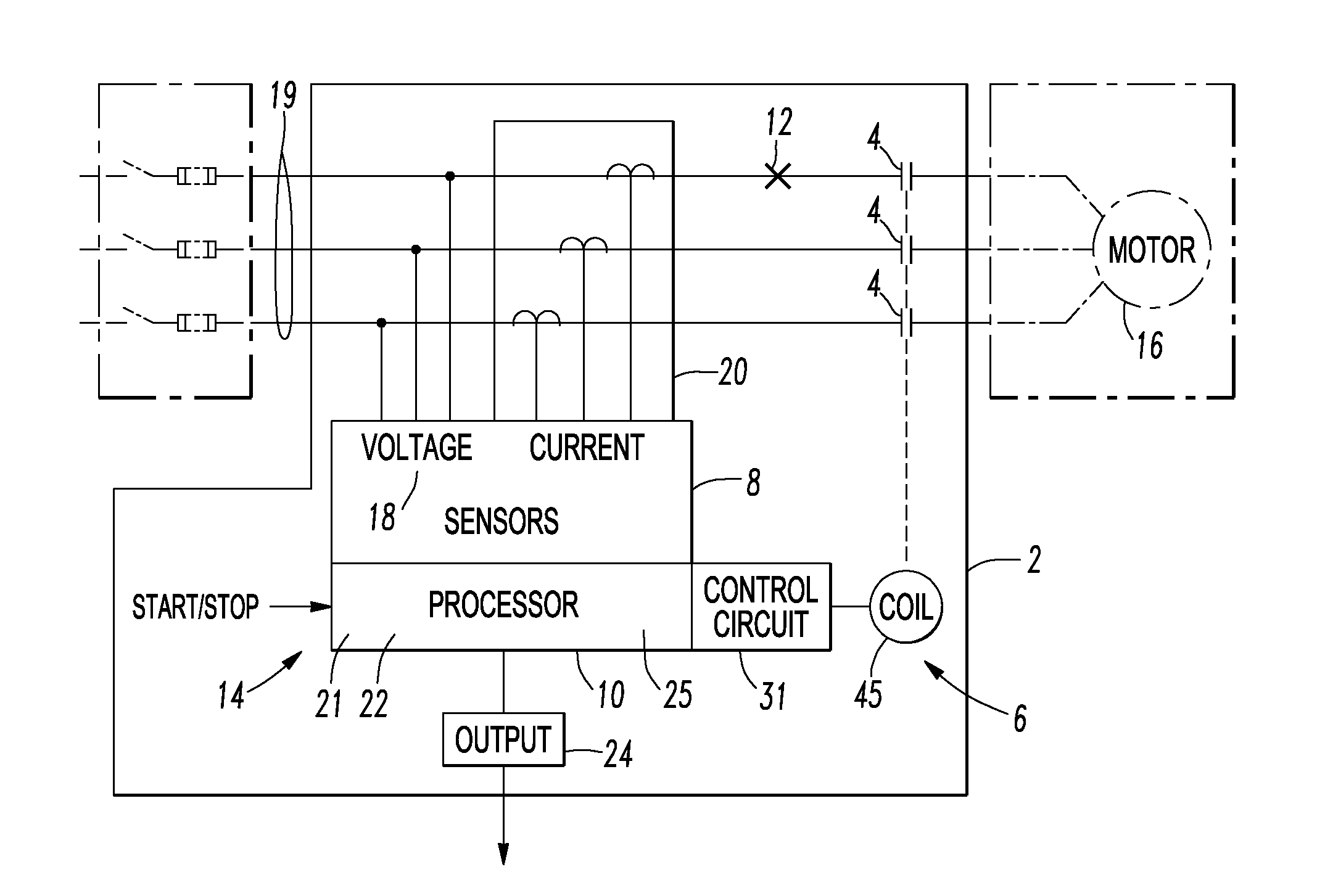
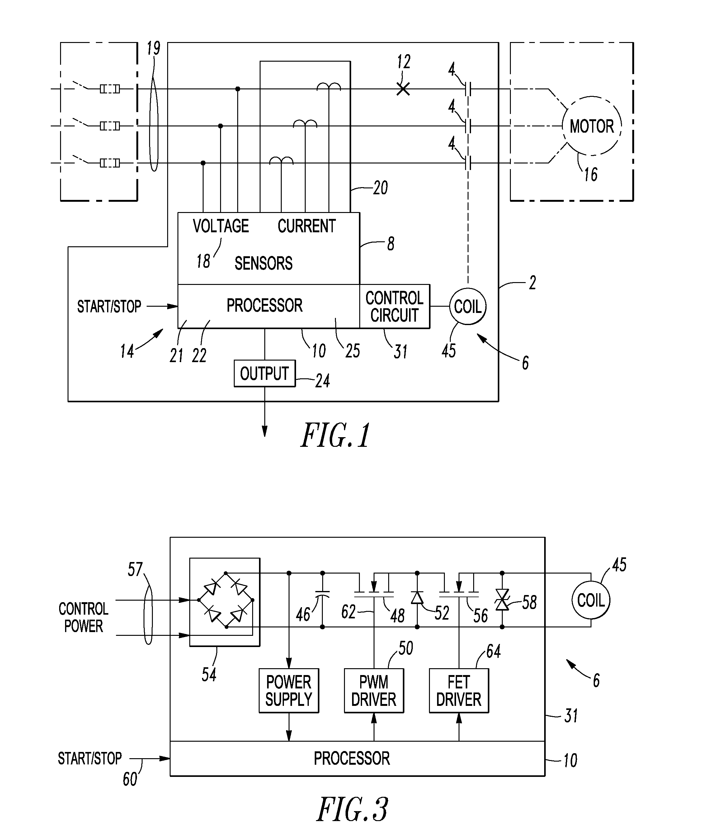
[0041]The output 24 can be an annunciator or a display cooperating with the processor 10 and displaying the determined fault current and a number of: (1) the incident energy at the example motor starter 2; and / or (2) the personal protective equipment (PPE) level operatively associated with the example motor starter 2.

example 2

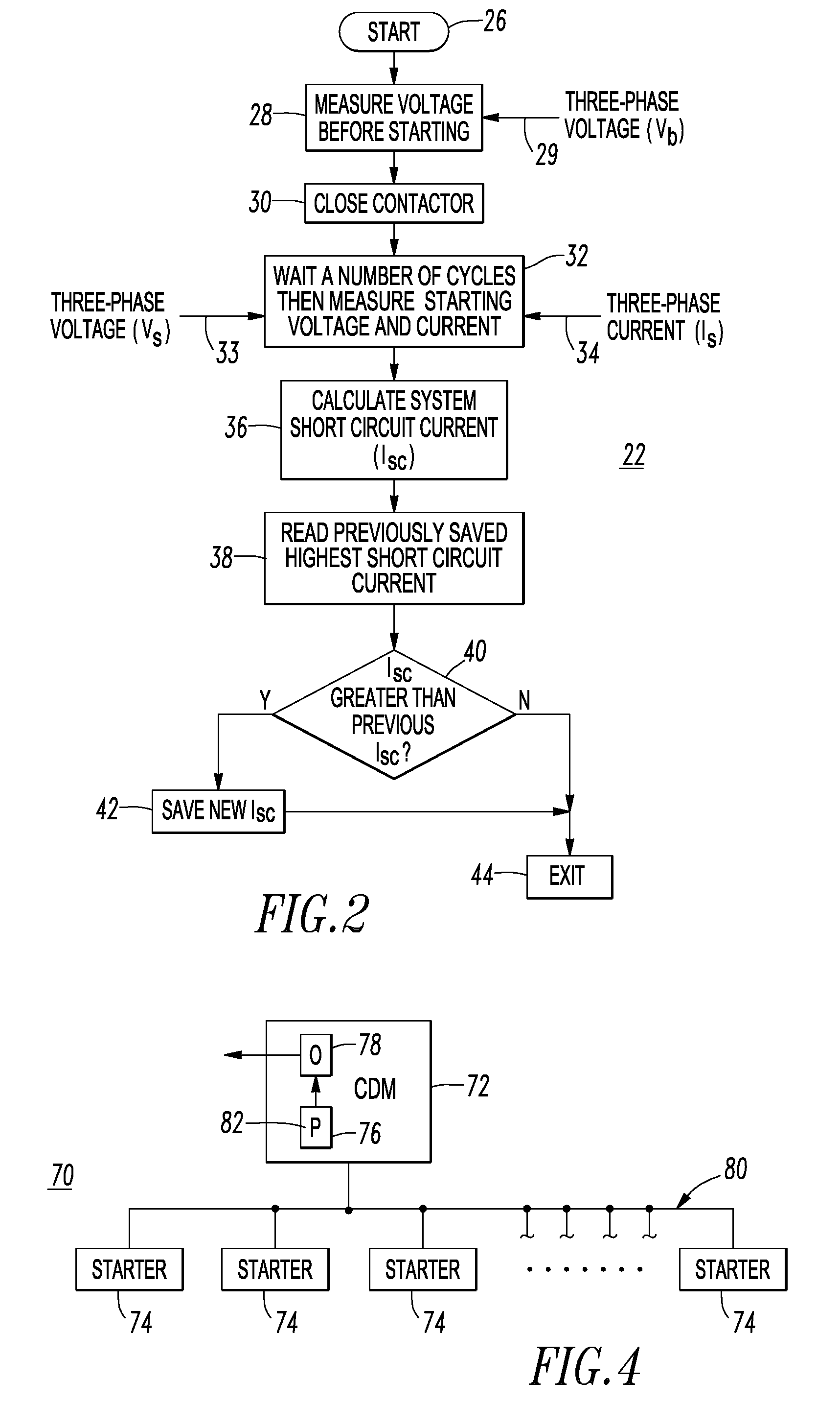
[0042]The output 24 can communicate with a communication network (e.g., 80 of FIG. 4), which can communicate to a local or remote location the determined fault current and a number of: (1) the incident energy at the example motor starter 2; and / or (2) the personal protective equipment (PPE) level operatively associated with the example motor starter 2.

example 3

[0043]The processor 10 can determine the personal protective equipment (PPE) level from a look-up table 25, which converts the incident energy at the example motor starter 2 to a corresponding PPE level.


PUM


Abstract

A protection relay for an electrical switching apparatus for a load includes a number of voltage sensors structured to sense voltage applied to the load, a number of current sensors structured to sense current flowing to the load, and a processor cooperating with the number of voltage sensors and the number of current sensors. The processor determines a fault current available at the load. An output cooperates with the processor. The output is structured to output the determined fault current and a number of: incident energy at the electrical switching apparatus, and a personal protective equipment level operatively associated with the electrical switching apparatus. The processor determines from the determined fault current the number of: the incident energy at the electrical switching apparatus, and the personal protective equipment level operatively associated with the electrical switching apparatus.

Description

BACKGROUND[0001]1. Field[0002]The disclosed concept pertains generally to electrical switching apparatus and, more particularly, to electrical switching apparatus for controlling a load. The disclosed concept also pertains to protection relays, such as motor protection relays, and to systems including controllers for controlling loads.[0003]2. Background Information[0004]Contactors are employed, for example and without limitation, in starter applications to switch on / off a load as well as to protect a load, such as a motor or other electrical device, from current overloads. Contactors are used as electrical switching apparatus and incorporate fixed and movable contacts that when closed, conduct electric power.[0005]A starter is a device used to provide protection and control for a load, such as a single-phase or three-phase motor and the like, typically used in, for example, various industrial settings to operate machinery. A common type of starter includes an electromagnetic contac...

Claims


Application Information

Patent Timeline
19 May 2011
Publication
US20110116196A1
IPC
H02H7/08; H02H3/00
CPC
H02H5/12; H02H1/0015; H02H7/0816
Inventors
KELLIS, JOE M.; FARR, LAWRENCE B.