Connector device, receiving connector, and inserting connector

a technology of receiving connectors and connectors, which is applied in the direction of three-pole connections, coupling device connections, electric discharge lamps, etc., can solve the problems of adverse effects on the operation of electric components and human body, and achieve the effect of high voltage and safe supply

Inactive Publication Date: 2011-05-19
FUJITSU COMPONENENT LTD
View PDF8 Cites 8 Cited by
  • Summary
  • Abstract
  • Description
  • Claims
  • Application Information

AI Technical Summary

Benefits of technology

[0010]Accordingly, embodiments of the present invention may provide a novel and useful connector device, receiving connector, and inserting connector solving one or more of the problems discussed above.
[0011]More specifically, the embodiments of the present invention may provide a connector device, a receiving connector, and an inserting connector whereby electric power having a high voltage can be safely supplied.

Problems solved by technology

With respect to the electric power supplied to the electronic device, if the voltage is high, a human body may be influenced or operations of electric components may be adversely affected.

Method used


Image

  • Connector device, receiving connector, and inserting connector
  • Connector device, receiving connector, and inserting connector
  • Connector device, receiving connector, and inserting connector

Examples


first embodiment

[0058]A connector device, a receiving connector and an inserting connector of a first embodiment of the present invention are discussed.

(Structures of the Connector Device, the Receiving Connector and the Inserting Connector)

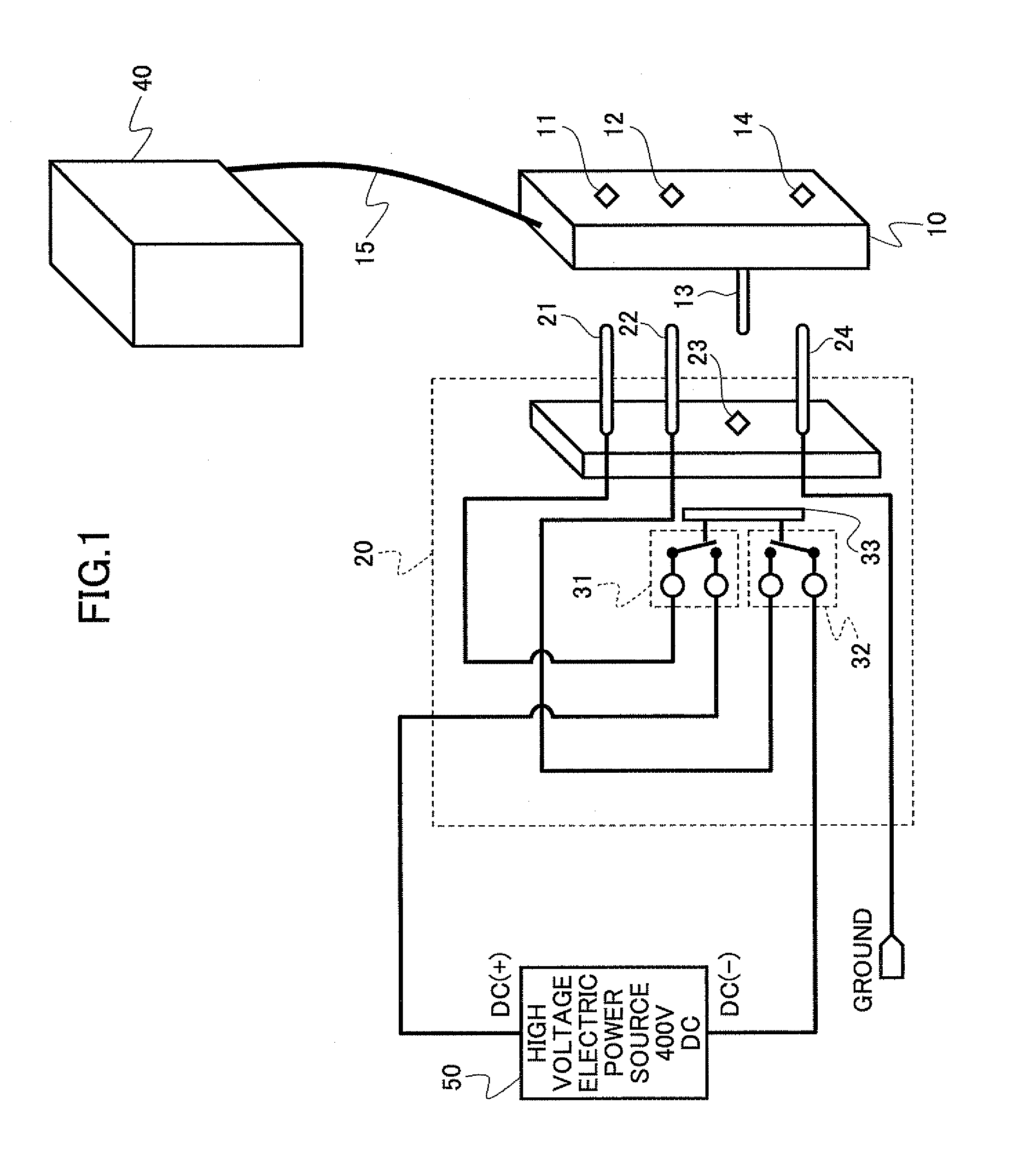
[0059]FIG. 1 is a schematic view of structures of the connector device, the receiving connector and the inserting connector of the first embodiment of the present invention.

[0060]The connector device of the first embodiment of the present invention includes a receiving connector 10 and an inserting connector 20.

[0061]The receiving connector 10 is connected to an information device 40 such as a server. The receiving connector 10 includes two electric power jack terminals 11 and 12 configured to receive a supply of the electric power, a control plug terminal 13, and a ground jack terminal 14. The control plug terminal 13 can be extended and retracted in an inserting direction of the receiving connector 10.

[0062]On the other hand, the inserting connector 20 is conn...

second embodiment

[0127]A second embodiment of the present invention relates to a receiving connector. More specifically, in the receiving connector, expansion and retraction of the control plug terminal is performed by a restoring force of a coil spring.

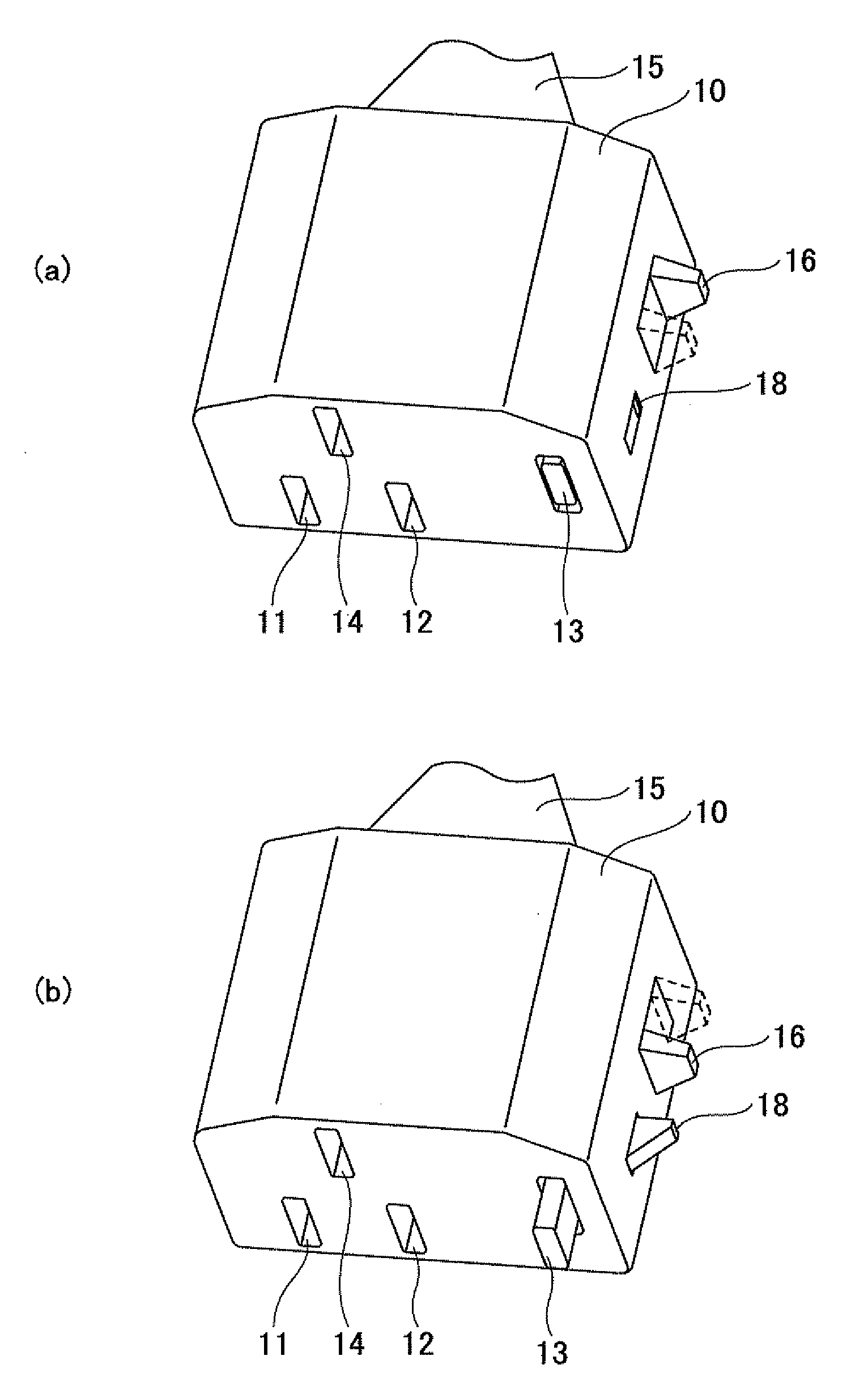
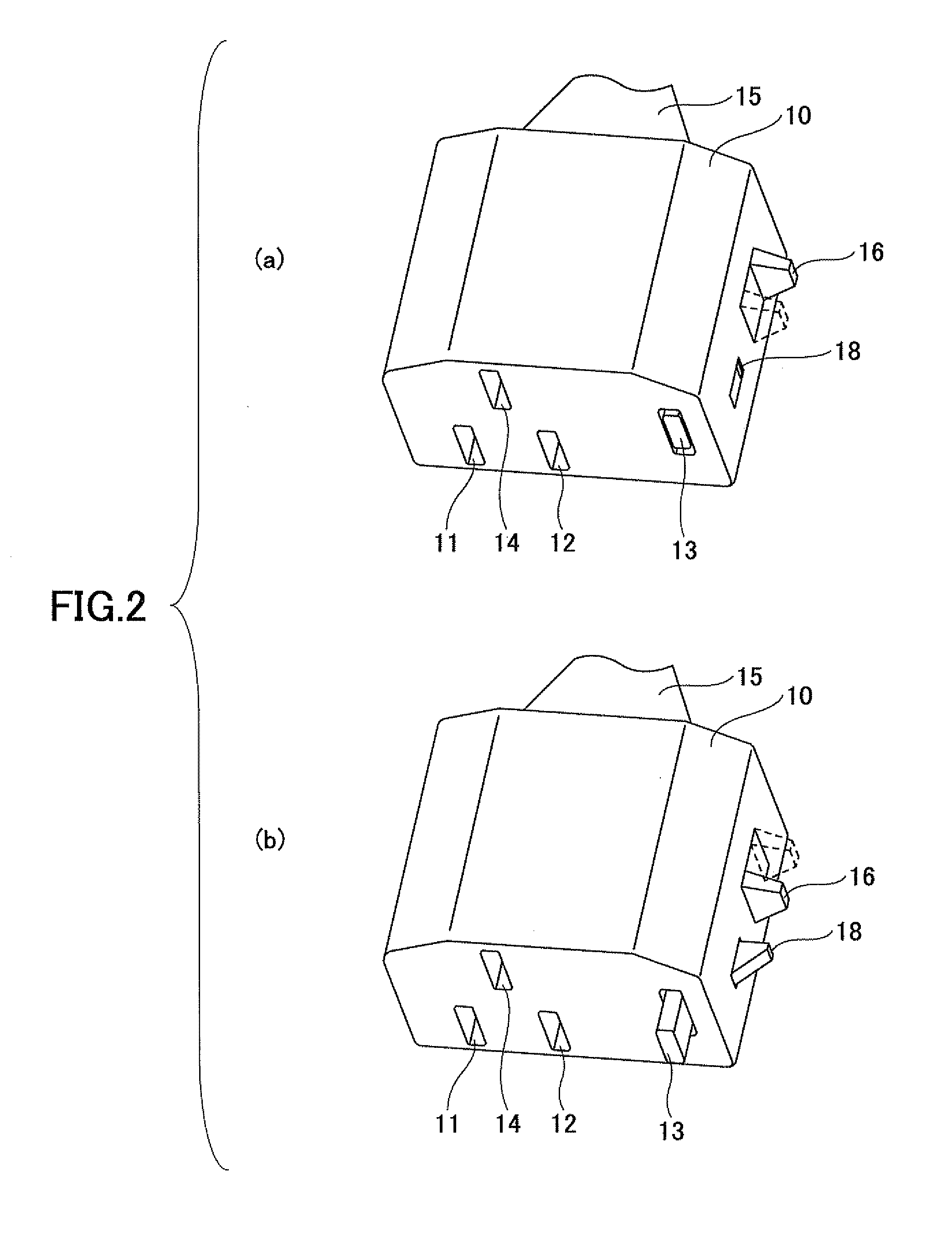
[0128]FIG. 15 shows a structure of a receiving connector of the second embodiment of the present invention. FIG. 15(a) is a perspective view of a receiving connector 110 in the retracted state where the control plug terminal 113 is retracted. FIG. 15(b) is a perspective view of a receiving connector 110 in the extended state where the control plug terminal 113 is extended.

[0129]The receiving connector 110 of the second embodiment of the present invention includes two electric power jack terminals 111 and 112 for receiving supply of the electric power, a control plug terminal 113, a ground jack terminal 114 for ground, a slide switch 116, and a lock terminal 108.

[0130]By sliding the slide switch 116 in the inserting direction of the control plug termi...

third embodiment

[0156]Next, a connector device, a receiving connector, and an inserting connector of a third embodiment of the present invention are discussed.

[0157]FIG. 18 is a structural view of the connector device, the receiving connector, and the inserting connector of the third embodiment of the present invention. In FIG. 18, parts that are the same as the parts shown in FIG. 1 through FIG. 14 are given the same reference numerals, and explanation thereof is omitted.

[0158]The connector device of the third embodiment of the present invention includes the receiving connector 10 and an inserting connector 220. The inserting connector 220 is connected to the high voltage electric power source 50 configured to supply electric power.

[0159]The receiving connector 220 includes the electric power plug terminals 21 and 22, the control jack terminal 23, and the ground plug terminal 24. The electric power plug terminals 21 and 22 correspond to the electric power jack terminals 11 and 12. The control jack...


PUM


Abstract

A connector device includes an inserting connector and a receiving connector, wherein the receiving connector is connected to the electronic device; the receiving connector includes a single control plug terminal and two electric power jack terminals made of a conductor material, the electric power jack terminals being configured to receive the supply of the electric power; the control plug terminal can be extended and retracted in an inserting direction of the receiving connector; the inserting connector is connected to the electric power source; the inserting connector includes a control jack terminal corresponding to the control plug terminal and two electric power plug terminals corresponding to the two electric power jack terminals; and the control jack terminal includes a control switch.

Description

CROSS-REFERENCE TO RELATED APPLICATIONS[0001]This patent application is based upon and claims the benefit of priority of Japanese Patent Application No. 2009-259731 filed on Nov. 13, 2009 the entire contents of which are incorporated herein by reference.BACKGROUND OF THE INVENTION[0002]1. Field of the Invention[0003]The present invention generally relates to connector devices, receiving connectors, and inserting connectors. More specifically, the present invention relates to a connector device, a receiving connector, and an inserting connector which are used for supplying electric power.[0004]2. Description of the Related Art[0005]It is general practice that electronic devices are operated by receiving supplies of electric power from electric power sources. It is also general practice that the electronic device receives the supply of the electric power from the electric power source via a connector device.[0006]In the connector device, as discussed in Japanese Laid-Open Patent Appli...

Claims


Application Information

Patent Timeline
Patent Type & Authority Applications(United States)
IPC IPC(8): H01R29/00
CPCH01R13/639H01R13/701H01R2105/00H01R24/76H01R24/28
Inventor BEAK, SEUNG SEOKKIRYU, KOICHIHIROSE, KEIICHIIINO, TOMONORI
Owner FUJITSU COMPONENENT LTD
Why Eureka
Try Eureka