
Supply device and method for a mobile imaging device

a technology of mobile imaging and supply device, which is applied in the field of mobile imaging device supply device and method, can solve the problems of affecting the stability of the wheel mounted medical device upon lateral c-arm movement, and affecting the patient's diagnosis. the effect of stability

Inactive Publication Date: 2018-09-25
GENERAL ELECTRIC CO
View PDF11 Cites 4 Cited by
  • Summary
  • Abstract
  • Description
  • Claims
  • Application Information

AI Technical Summary

Benefits of technology

This solution enhances workflow flexibility for healthcare personnel, ensures continuous supply of essential media to patients, reduces the risk of cable collisions, and maintains patient safety during imaging procedures by maintaining cable connections and preventing accidental disconnections.

Problems solved by technology

Since the C-arm needs to rotate around the patient there is the risk that objects as a supply cable connected to the patient collide or gets entangled with the x-ray source or the x-ray detector.
However, in the case that the supply cable is configured for continuous perfusion delivery to the patient, the perfusion needs to be linked to the patient and never removed during surgery.
Hence, there is the problem that health professionals need to direct their attention to the maintenance of continuous supply of the patient with perfusion or the like and cannot exclusively follow the surgery or any other interventional procedures.
There is further a risk of pain or discomfort of the patient, if an anaesthetic supply cable falls off due to movements of the C-arm.
Moreover, tissue of the patient may be damaged due to uncontrolled tearing off a cable from an intravascular access.
Due to collision with a C-arm member a mobile perfusion stand may tip over and fall on a medical health professional or the operation table, thus endangering an ongoing surgical intervention.

Method used


Image

  • Supply device and method for a mobile imaging device
  • Supply device and method for a mobile imaging device
  • Supply device and method for a mobile imaging device

Examples


Embodiment Construction

[0029]The present disclosure relates to the field of medical imaging devices and more particularly, to a device and method for supplying at least one medium to an object of interest, which is scanned by a mobile imaging device. In particular, the present disclosure relates to an imaging device comprising a movable C-arm with an x-ray system for scanning the object of interest such as a patient and a cable for supplying a perfusion or any other medium, such as a fluid medium (liquid and / or gas) to the object of interest.

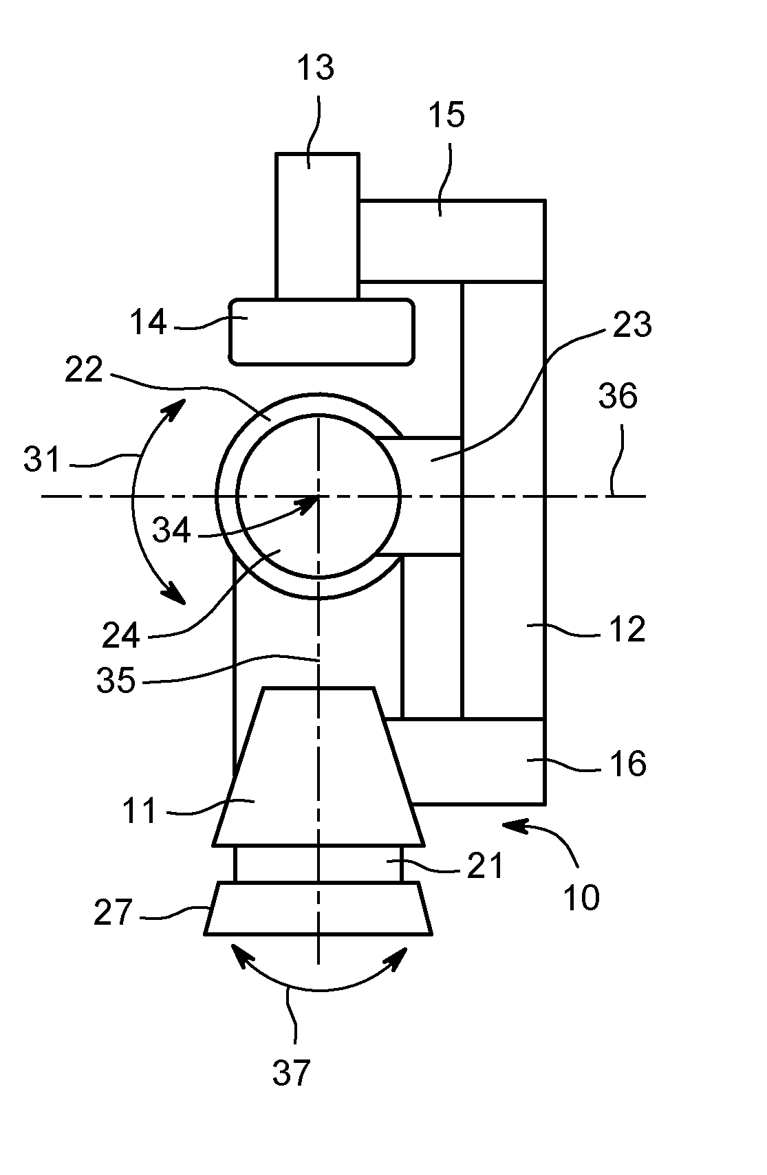
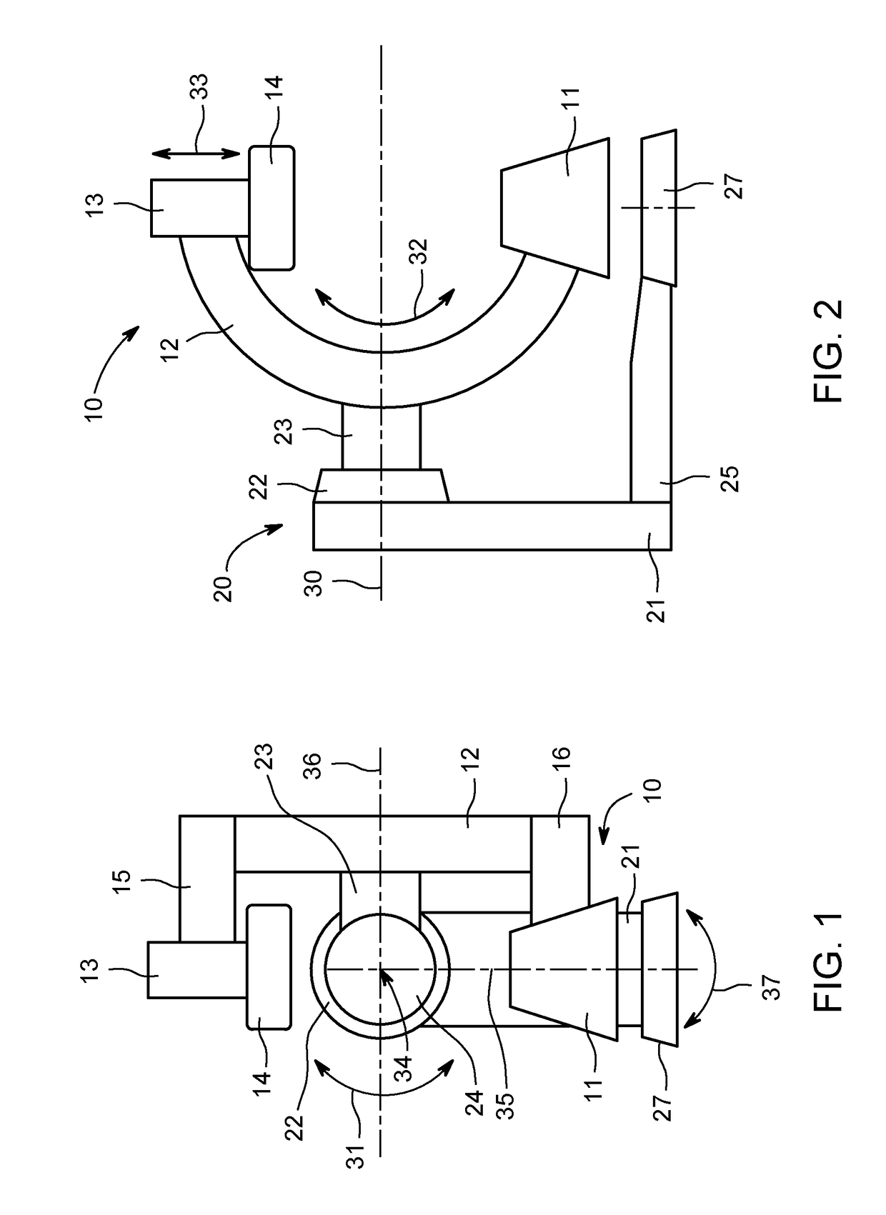
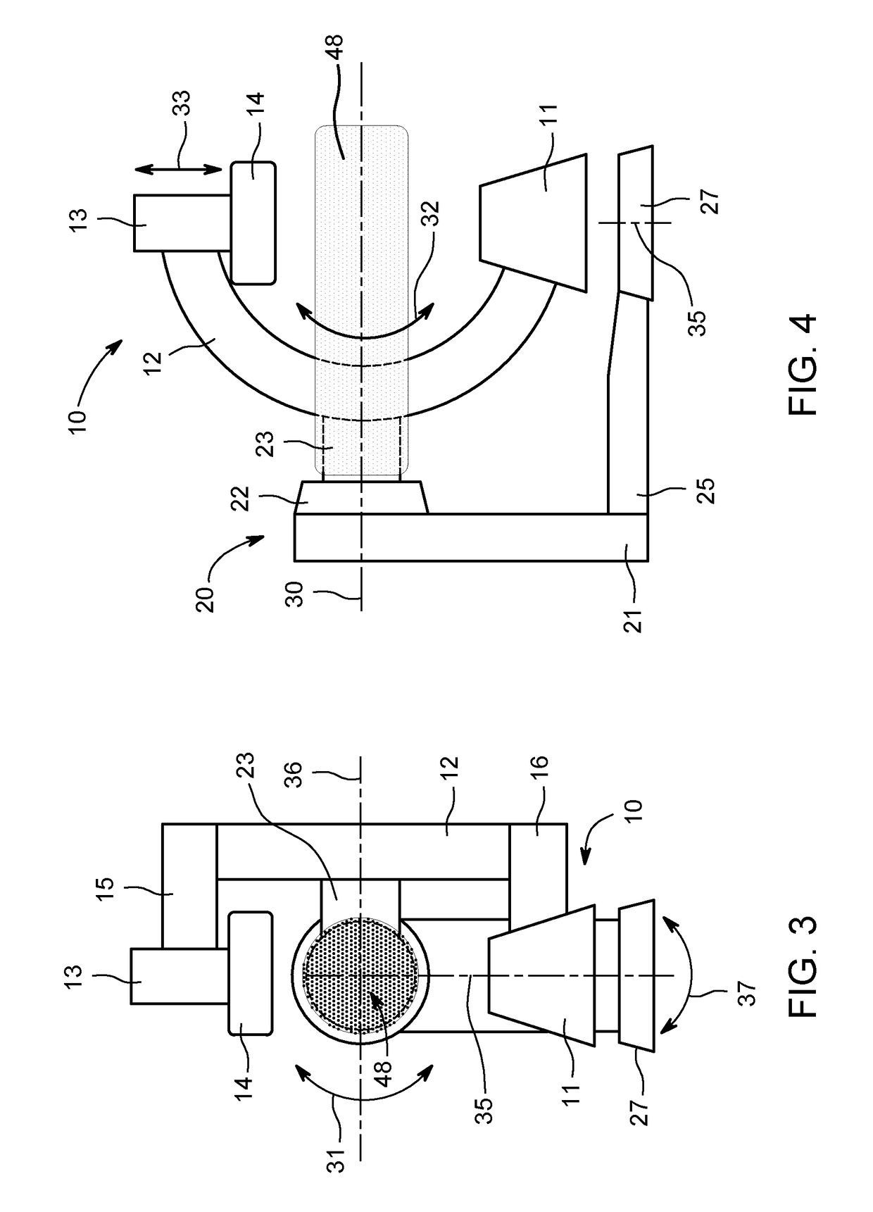
[0030]A mobile C-arm device is diagrammatically illustrated in FIG. 1, wherein the medical device is generally marked with the reference numeral 10. The medical imaging device 10 includes an arc-shaped member 12 (C-arm). The so called C-arm 12 terminates in opposing distal ends. The C-arm 12 has preferably a uniformly circular C-shape that may alternatively comprise any arc-shaped member.

[0031]As can be seen in the front view of FIG. 1 the medical device 10 comprises ...


PUM


Abstract

A device and method are provided for supplying a medium to an object of interest, such as a patient to be scanned for image acquisition. The device comprises an arc-shaped member and a support for said arc-shaped member, wherein the arc-shaped member is configured to support a radiation source on one end and a detector on another end to scan the object of interest, and the support comprises a gantry with a rotatable support arm supporting the arc-shaped member. The device further comprises at least one medium supply unit mounted on the gantry. The supply unit is connectable to a cable that is guided in the vicinity or in the region of the axis of rotation of the support arm so that the object of interest can be supplied with a perfusion or any other medium, while enabling the mobile imaging device to rotate around the patient to acquire x-ray images.

Description

BACKGROUND[0001]Healthcare practice has shown the value of taking images as x-rays of a patient from a number of different positions. The use of medical imaging acquisition systems has improved the diagnosis and care of patients. Currently available x-ray imaging systems can be used in operating rooms, intensive care departments or emergency rooms. One type of device uses a mobile C-arm which is rotated to provide the necessary scanning views. Mobile C-arm x-ray diagnostic equipment has been developed to enable a physician to treat or otherwise attend to the patient without the need to repeatedly remove and replace the x-ray equipment. More particularly, mobile C-arm x-ray equipment has been developed for surgical and other interventional procedures. Mobile C-arm x-ray image acquisition devices can be used for well-defined surgical planning and guiding surgical interventions. During surgeries the space immediately surrounding the patient should not be unduly encumbered in order to e...

Claims


Application Information

Patent Timeline
Patent Type & Authority Patents(United States)
IPC IPC(8): A61B5/00A61B6/00A61B6/10A61B6/04
CPCA61B6/4441A61B6/102A61B6/507A61B6/4405A61B6/0407
Inventor MARGOT, PAUL VINCENT
Owner GENERAL ELECTRIC CO
Learn More