Direct-current voltage supply circuit

Active Publication Date: 2020-05-07
MURATA MFG CO LTD
View PDF0 Cites 4 Cited by
  • Summary
  • Abstract
  • Description
  • Claims
  • Application Information

AI Technical Summary

Benefits of technology

[0027]In the direct-current voltage supply circuits of preferred embodiments of the present invention, even when, after abnormal heating is detected and the supply of direct-current voltage through the power line is stopped, the temperature detector naturally cools down and decreases in temperature, since the state holding circuit holds

Problems solved by technology

However, if the supply of direct-current voltage is resumed before such a cause as short circuit is resolved, overcurrent or abnormal heating occurs again.
If the supply of direct-cu

Method used


Image

  • Direct-current voltage supply circuit
  • Direct-current voltage supply circuit
  • Direct-current voltage supply circuit

Examples


first preferred embodiment

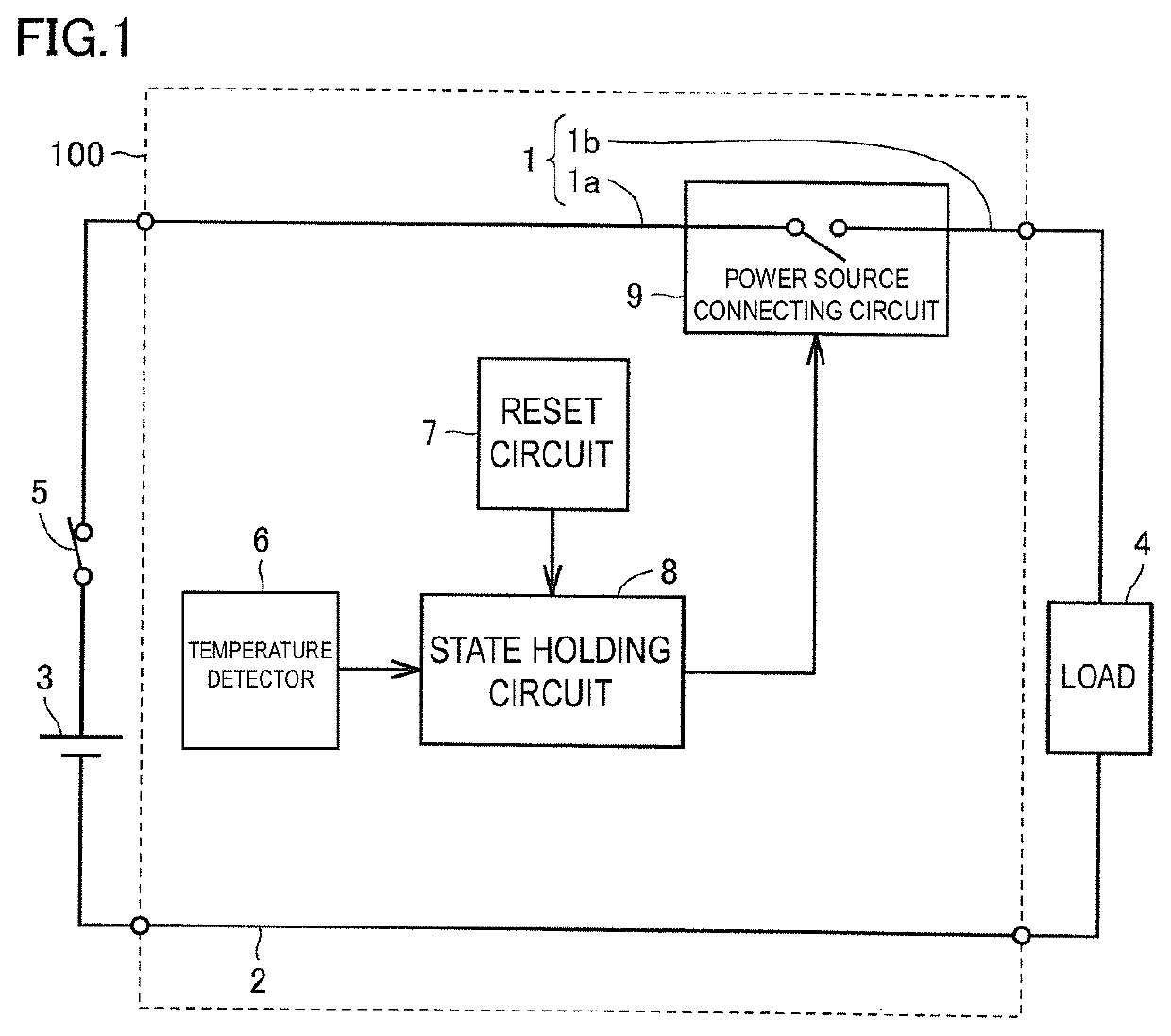
[0052]FIG. 1 is a functional block diagram of a direct-current voltage supply circuit 100 according to a first preferred embodiment of the present invention. Referring to FIG. 1, the direct-current voltage supply circuit 100 includes a power line 1 and a ground line 2, a state holding circuit 8, a power source connecting circuit 9, a temperature detector 6, and a reset circuit 7. The power line 1 includes a power switch 5, which is optional.

[0053]The power line 1 and the ground line 2 are inserted between a direct-current power source 3 and a load 4. The state holding circuit 8 is capable of being in either a first state or a second state.

[0054]The power source connecting circuit 9 is disposed in at least one of the power line 1 and the ground line 2. Although FIG. 1 illustrates an example where the power source connecting circuit 9 is disposed in the power line 1, the power source connecting circuit 9 may be disposed in the ground line 2 instead of the power line 1, or may be dispo...

second preferred embodiment

[0100]FIG. 5 is a circuit diagram of a direct-current voltage supply circuit 200 according to a second preferred embodiment of the present invention. Note that FIG. 5 is an equivalent circuit diagram of the direct-current voltage supply circuit 200.

[0101]The direct-current voltage supply circuit 200 is obtained by modifying a portion of the direct-current voltage supply circuit 100 according to the first preferred embodiment illustrated in FIG. 4.

[0102]In the direct-current voltage supply circuit 100 described above, the temperature detector 6 includes the first fixed resistor R1 and the positive temperature coefficient thermistor PTC that are connected in series. The temperature detector 6 is connected to the power line 1 at one end thereof adjacent to the first fixed resistor R1, and is connected to the ground line 2 at the other end thereof adjacent to the positive temperature coefficient thermistor PTC. The direct-current voltage supply circuit 200 is obtained by modifying this ...

third preferred embodiment

[0105]FIG. 6 is a diagram illustrating a configuration of a direct-current voltage supply circuit 300 according to a third preferred embodiment of the present invention. Note that FIG. 6 is an equivalent circuit diagram of the direct-current voltage supply circuit 300.

[0106]The direct-current voltage supply circuit 300 is also obtained by modifying a portion of the direct-current voltage supply circuit 100 according to the first preferred embodiment.

[0107]The direct-current voltage supply circuit 300 includes a first capacitor C1 connected in parallel with the positive temperature coefficient thermistor PTC of the temperature detector 6, which is included in the direct-current voltage supply circuit 100. The direct-current voltage supply circuit 300 also includes a second capacitor C2 connected between the node Y and the ground line 2, and a third capacitor C3 connected between the power line 1a adjacent to the direct-current power source 3 and the ground line 2. Additionally, the d...


PUM


Abstract

A direct-current voltage supply circuit includes a first field effect transistor in a power line, a voltage divider including a first fixed resistor and a positive temperature coefficient thermistor between the power line and a ground line, a thyristor connected at an anode thereof to the power line, with a second field effect transistor interposed therebetween, connected at a gate thereof to a node in the voltage divider, and connected at a cathode thereof to the ground line, with a second fixed resistor interposed therebetween, and a third fixed resistor connected in parallel with the thyristor and the second field effect transistor. If abnormal heating increases the resistance of the positive temperature coefficient thermistor, the first field effect transistor is turned off and the supply of direct-current voltage is stopped.

Description

CROSS REFERENCE TO RELATED APPLICATIONS[0001]This application claims the benefit of priority to Japanese Patent Application No. 2017-147118 filed on Jul. 28, 2017 and Japanese Patent Application No. 2017-152377 filed on Aug. 7, 2017, and is a Continuation Application of PCT Application No. PCT / JP2017 / 031109 filed on Aug. 30, 2017. The entire contents of each application are hereby incorporated herein by reference.BACKGROUND OF THE INVENTION1. Field of the Invention[0002]The present invention relates to a direct-current voltage supply circuit that supplies a direct-current voltage from a direct-current power source to a load. More specifically, the present invention relates to a direct-current voltage supply circuit having a safer protective function against abnormal heating.2. Description of the Related Art[0003]If overcurrent or abnormal heating occurs in a direct-current voltage supply circuit that supplies a direct-current voltage from a direct-current power source to a load, it ...

Claims


Application Information

Patent Timeline
IPC IPC(8): H02H5/04
CPCH02H5/042H02J7/00H02H3/085
Inventor YAMANE, RIEKATO, TADASHI
Owner MURATA MFG CO LTD
Why Eureka
Try Eureka