
Vehicle And Method For Controlling Engine Start In A Vehicle

a technology for starting and accelerating engines, applied in the direction of engine starters, electric control, instruments, etc., can solve problems such as torque disturbances, and achieve the effect of removing torque disturbances

Active Publication Date: 2011-05-19
FORD GLOBAL TECH LLC
View PDF43 Cites 82 Cited by
  • Summary
  • Abstract
  • Description
  • Claims
  • Application Information

AI Technical Summary

Benefits of technology

[0006]Embodiments of the present invention include a vehicle having an engine, an electric machine, for example, a traction motor, or a motor / generator (M / G), that can output torque to the engine and to the vehicle wheels, and a starter motor operatively connected to the engine. The starter motor can be used to provide torque to start the engine without the addition of torque from the M / G. This isolates the M / G during engine start and eliminates torque disturbances that would otherwise occur when torque was transferred from the M / G to the engine to assist the engine start.
[0008]Although the present invention, which exclusively relies on the starter motor to provide engine starting torque, may be best suited for a direct injection (DI) engine, it can also be used with other types of engines, such as a port injection engine. In addition, vehicles and methods of the present invention may function more efficiently when the engine crankshaft is stopped at a predetermined position, or within a predetermined range of positions, rather than at a random angular position. This can facilitate a more efficient, easier engine start when only the starter motor is used for engine start.
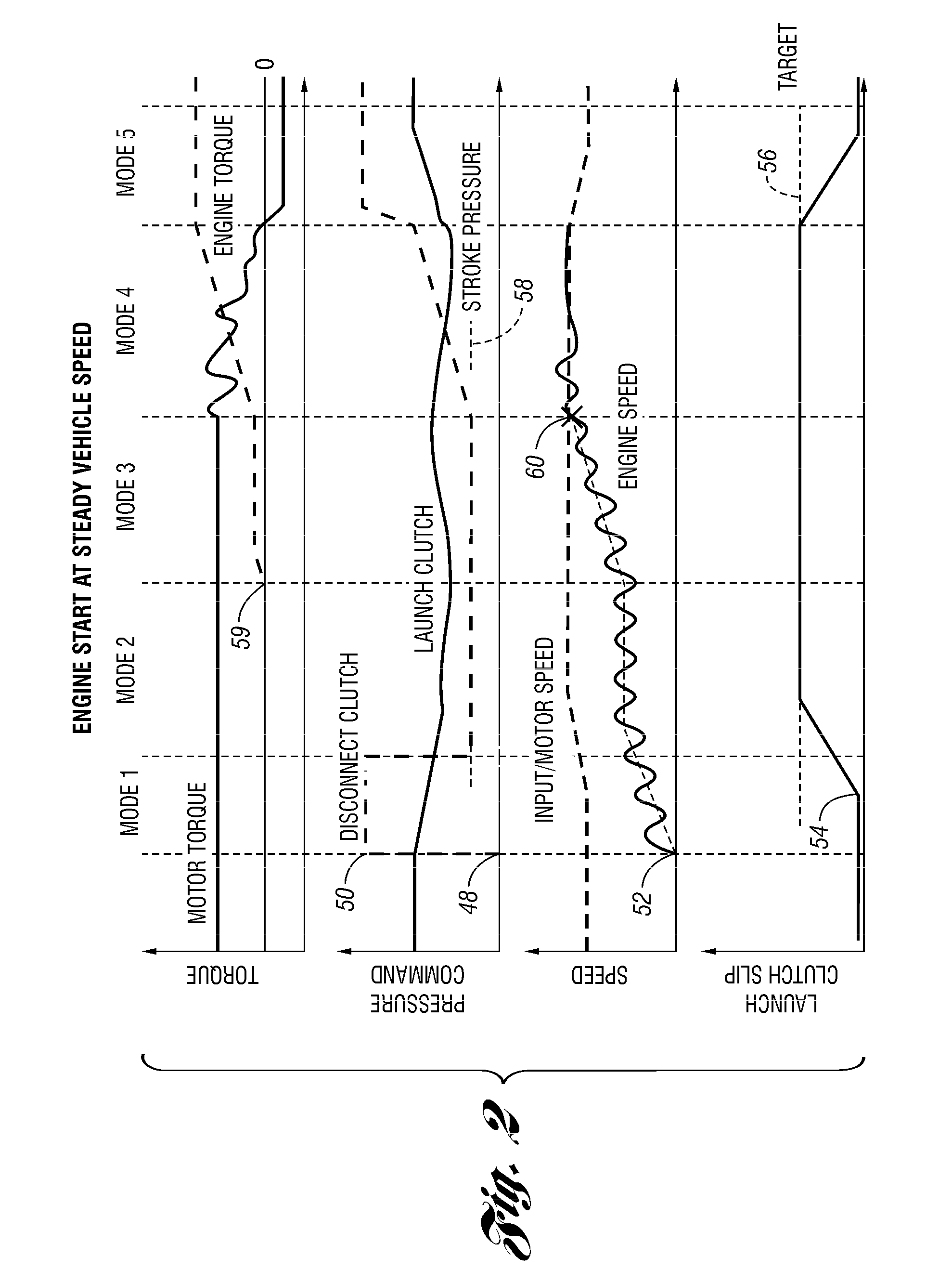
[0010]The pressure in the disconnect clutch can then be reduced to a second level to what is commonly referred to as a “stroke pressure”. The stroke pressure is the amount of pressure necessary to move a clutch piston or the clutch plates to just at the point of contact. At the stroke pressure, the clutch is slipping, but it is ready to be quickly engaged. In this way, the M / G is ostensibly isolated from the engine, and the vehicle occupants will not be subject to torque disturbances resulting from torque being transferred from the M / G to the engine during engine start.

Problems solved by technology

This can be particularly problematic when the engine is first being cranked because this is when the engine torque requirements are highest and torque disturbances can occur.

Method used


Image

  • Vehicle And Method For Controlling Engine Start In A Vehicle
  • Vehicle And Method For Controlling Engine Start In A Vehicle
  • Vehicle And Method For Controlling Engine Start In A Vehicle

Examples


Embodiment Construction

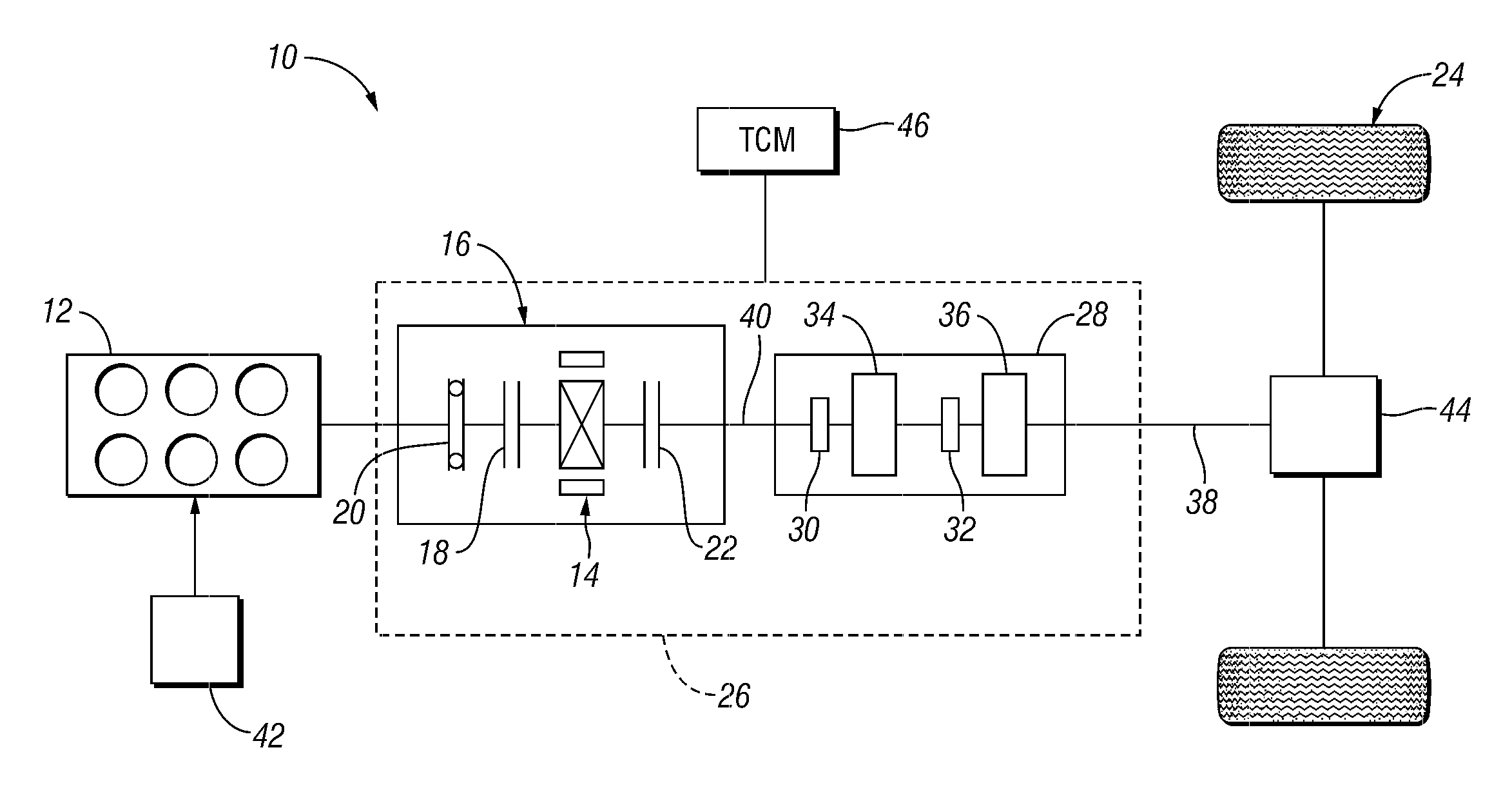
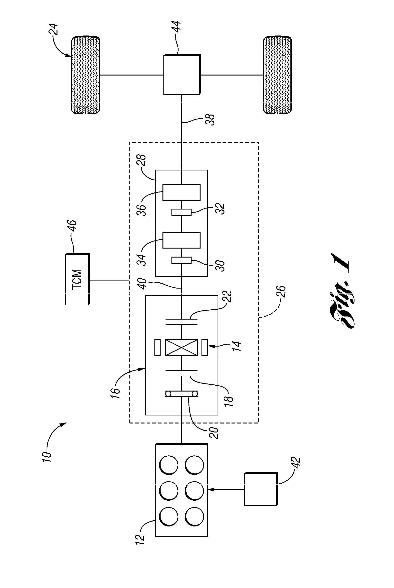
[0023]FIG. 1 shows a schematic diagram of the vehicle 10 in accordance with the present invention. The vehicle 10 is an HEV, and includes an engine 12, and an electric machine, which, in the embodiment shown in FIG. 1, is a M / G 14. The M / G 14 is part of a clutch / motor housing 16 that further includes a first clutch 18, or disconnect clutch and a damper 20 disposed between the disconnect clutch 18 and the engine 12. The damper 20 may be, for example, a series of plates and springs configured to help dampen changes in torque transferred between the engine 12 and the M / G 14 when the disconnect clutch 18 is being engaged. The clutch / motor housing 16 also includes a launch clutch 22, which, as described in more detail below, can be controlled to isolate the M / G 14 from vehicle drive wheels 24. Although the clutches 18, 22 are described and illustrated as hydraulic clutches, other types of clutches, such as electromechanical clutches may also be used.

[0024]The clutch / motor housing 16 is p...


PUM


Abstract

A vehicle includes a motor / generator, a starter motor, a disconnect clutch disposed between the engine and the motor / generator, and at least one clutch disposed between the motor / generator and the vehicle drive wheels. When an engine start is requested, various parameters are controlled to ensure a smooth engine start wherein driveline torque disturbances are minimized. The starter motor is used to crank the engine upon an engine start request, thereby eliminating the need to transfer torque from the motor / generator to the engine. This helps to further reduce torque disturbances in the driveline when the engine is started.

Description

BACKGROUND OF THE INVENTION[0001]1. Field of the Invention[0002]The present invention relates to a vehicle and a method for controlling engine start in a vehicle.[0003]2. Background Art[0004]Hybrid electric vehicles (HEV's) utilize a combination of an internal combustion engine with an electric motor to provide the power needed to propel a vehicle. This arrangement provides improved fuel economy over a vehicle that has only an internal combustion engine. One method of improving the fuel economy in an HEV is to shutdown the engine during times that the engine operates inefficiently, and is not otherwise needed to propel the vehicle. In these situations, the electric motor is used to provide all of the power needed to propel the vehicle. When the driver power demand increases such that the electric motor can no longer provide enough power to meet the demand, or if the battery state of charge (SOC) drops below a certain level, the engine must start quickly and smoothly in a manner that...

Claims


Application Information

Patent Timeline
Patent Type & Authority Applications(United States)
IPC IPC(8): G06F19/00F02N11/08
CPCB60K6/48Y02T10/6286B60W10/06B60W10/08B60W20/00B60W30/192F02D41/023F02D41/062F02N11/006F02N11/08F02N11/0844F02N11/0848F02N15/022F02N2300/102Y02T10/6221B60W10/02Y02T10/62B60W30/19
Inventor ORTMANN, WALTER JOSEPHCOLVIN, DANIEL SCOTTMASTERSON, BRANDON R.BALDWIN, REID ALANSILVERI, ANDREW JOHNCONNOLLY, FRANCIS T.KRASKA, MARVIN PAUL
Owner FORD GLOBAL TECH LLC
Learn More