Solar photovoltaic support and tracking system with vertical adjustment capability

a technology tracking system, which is applied in the direction of comonautical navigation instruments, optical radiation measurement, instruments, etc., can solve the problems of increasing the horizontal load generated by local wind conditions, reducing the vertical load of solar photovoltaic support, and reducing the shading of one collector.

Inactive Publication Date: 2011-05-26
SILVER CHARLES
View PDF15 Cites 33 Cited by
  • Summary
  • Abstract
  • Description
  • Claims
  • Application Information

AI Technical Summary

Benefits of technology

It is a still further object of the present invention to provide a solar energy system which reduces or prevents shading of one collector by another.
It is also an object of the present invention to provide a solar energy system in which pole heights are increased to provide an improved method of avoiding obstacle shading while maintaining the ability to be lowered in adverse wind conditions.
It is still another object of the present invention to provide a solar energy system which can advantageously incorporate a dual axis tracking head.

Problems solved by technology

In particular, wind, solar thermal and solar photovoltaic technologies have been seen to positively affect all of these issues.
Given the need and desire to deploy solar energy collection systems, especially solar photovoltaic systems, it is known that certain obstacles exist.
One of the most significant of these obstacles is the need to render the “footprint” of such systems as small as possible.
However, the larger the solar photovoltaic array, the greater is the horizontal load generated by local wind conditions.
Furthermore, the need to design for high wind loads adds to the overall cost of the system by requiring heavier duty construction elements.
These systems tend to be fixed, that is, once installed, they are not orientable.
Unfortunately for such fixed systems, the sun moves from east to west during the day and from more nearly overhead positions during the summer to more nearly horizontally positions during the winter.
These variations in solar position make fixed systems significantly less efficient.
Roof mounting of solar panels, as opposed to post-mounted systems, exhibit several problems that militate against their use.
Firstly, a roof may be oriented in a direction that does not allow significant southern exposure (northern exposure in the southern hemisphere).
The roof may also be tilted poorly with respect to light capture.
The roof may also be too small to accommodate the desired number or weight of solar panels.
The roof may also be lacking in structural strength sufficient to accommodate the desired solar panel weight.
Additionally, roof mounting not only makes panel maintenance difficult but also potentially unsafe.
Roof maintenance or replacement is also made more complicated and often involves removal and reinstallation of the solar panels.
It should also be noted that photovoltaic systems are sensitive to thermal conditions in that higher substrate temperatures lead to lower energy output.
It is noted that even if one were to provide a tracking system which, on a daily basis, simply rotated a solar photovoltaic array about an axis perpendicular to the ground, this would still be less than 100% efficient since the sun courses through an arc well above the horizon.
However, systems for tracking are expensive, often adding from about $4,000.00 to about $7,000.00 to the cost of each post-mounted array, with the lower number being more likely to be able to only purchase a single-axis tracking system.
This represents a significant fixed cost that leads many otherwise interested parties to eschew solar photovoltaic systems.
In other words, the cost of entry becomes too high for many.
From the above, it is seen that fixed solar photovoltaic systems have limitations.
Additionally, the use of a concrete (or cement) base adds to the time it takes to install a new solar photovoltaic system.
This installation modality is thus seen to be not only labor intensive and thus costly, it is also seen to take time while the concrete is cured to a point where it is capable of supporting the mast and the array.

Method used


Image

  • Solar photovoltaic support and tracking system with vertical adjustment capability
  • Solar photovoltaic support and tracking system with vertical adjustment capability
  • Solar photovoltaic support and tracking system with vertical adjustment capability

Examples


Embodiment Construction

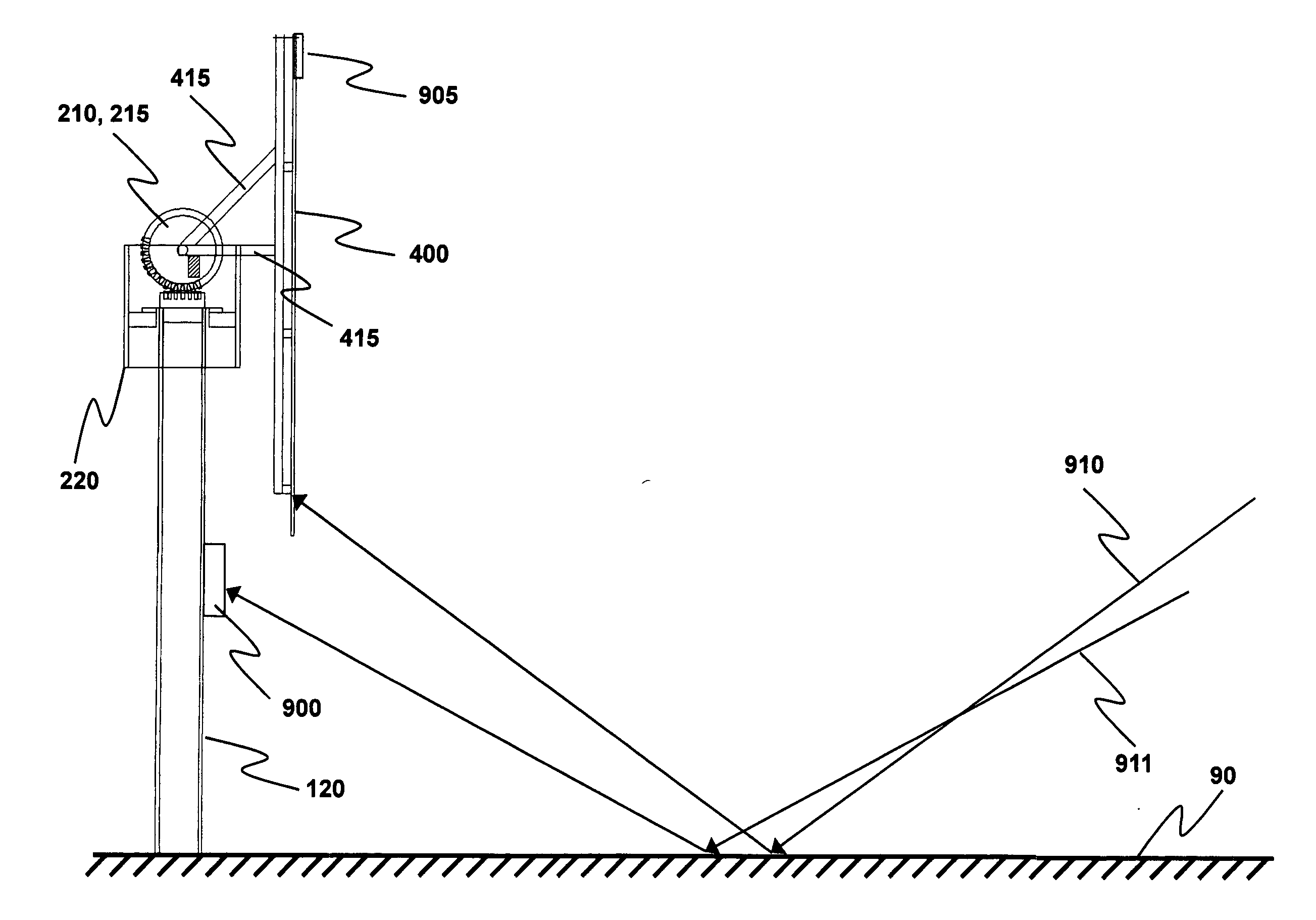
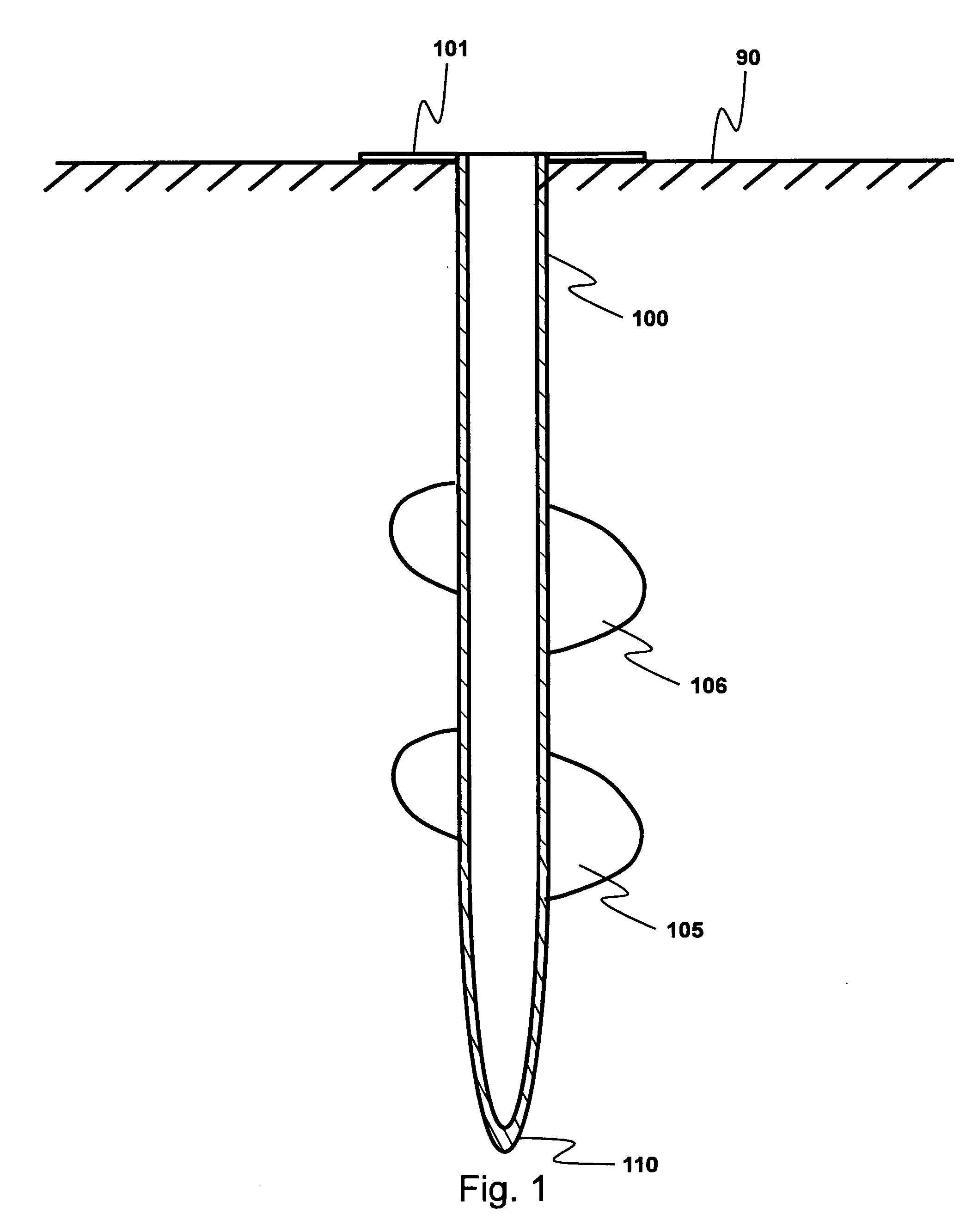
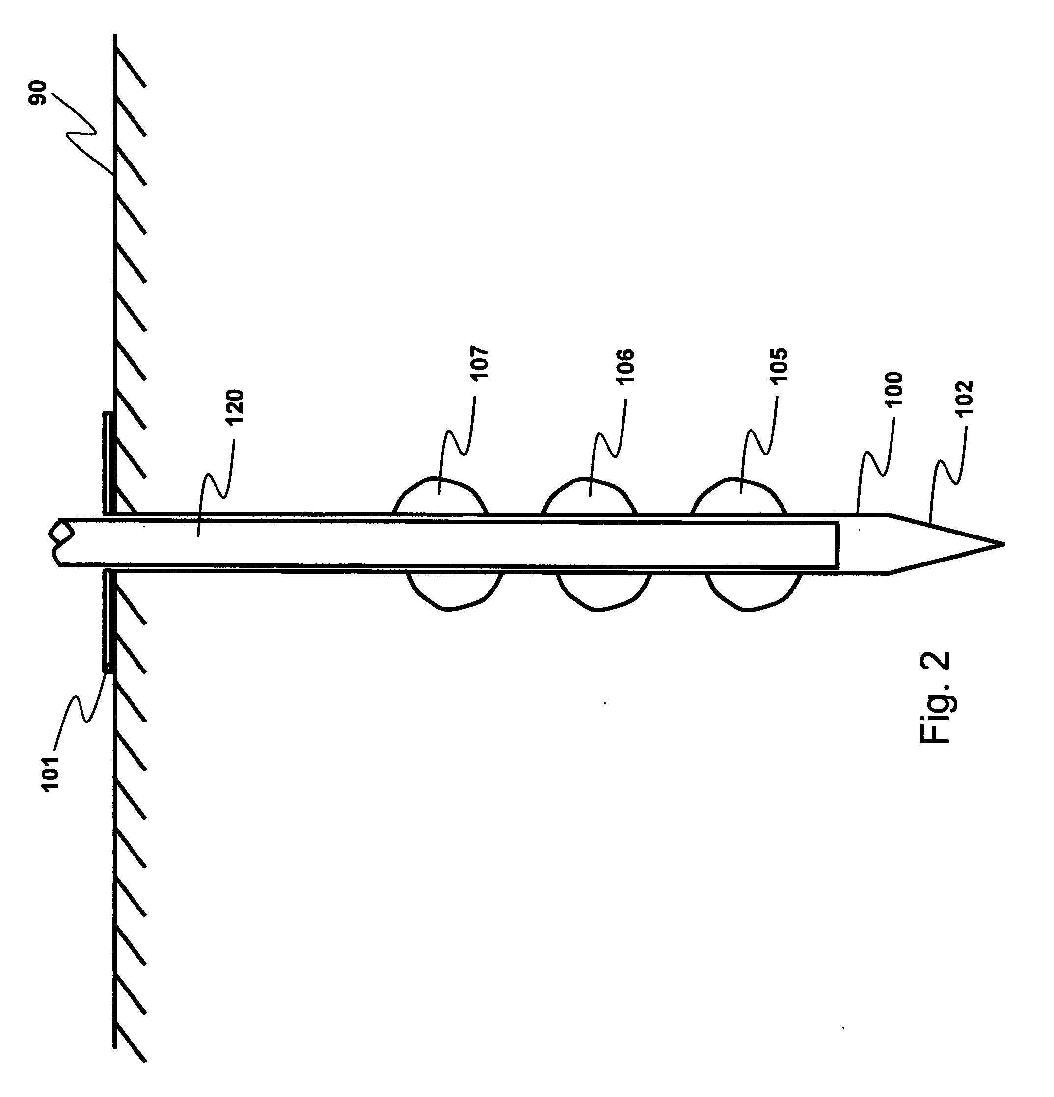
There are multiple aspects to the present invention. Nonetheless, the features disclosed herein may usually be employed independently of one another. It is, however, preferable to employ all of them simultaneously to provide an array of solar collectors which are easily, quickly and economically installed while at the same time providing an array system for which shading problems are either reduced or eliminated and while also providing a flexibly controllable dual axis tracking system. It is noted, however, that the augur system for installation may be employed whether or not a tracking or telescoping system is employed. Likewise, the telescoping system may be employed in more standard poured foundation systems whether or not the tracking head described herein is employed. The tracking head described herein may also be employed whether or not an augur base or telescoping poles are employed. In general, though, it is preferred that all of these features be deployed in the same syste...


PUM


Abstract

Installation of solar energy systems is made easier through the use of augur tubes. The base augur tube accommodates telescoping sections which enable these systems to exhibit a smaller footprint with enhanced power ratings. A tracking head is provided in which dual axis tracking is provided using a single drive mechanism. These features are employed either together or independently.

Description

TECHNICAL FIELDThe present invention is generally directed to solar photovoltaic energy systems. More particularly, the present invention is directed to methods and systems which provide economic and efficient solar photovoltaic generation system installations and structures. Even more particularly, the present invention is directed to the construction, structure and installation of solar photovoltaic systems in multi-post configurations that address the issue of installation area (especially as measured in terms of square feet per kilowatt-hour). Additionally, the present invention is directed to providing a dual axis tracking mechanism that works in a cooperative fashion with the installation and structural features of the invention. The present invention is also directed to single-post solar energy systems disposed in locations where wind conditions or obstruction avoidance are issues.BACKGROUND OF THE INVENTIONIssues of energy independence, global warming, the reduction of green...

Claims


Application Information

Patent Timeline
Patent Type & Authority Applications(United States)
IPC IPC(8): H01L31/042F24S50/20
CPCF24J2/0015F24J2/38F24J2/525F24J2/5266H02S20/00G01S3/7861Y02E10/47Y02E10/50F24J2/542F24S20/25F24S25/617F24S30/20F24S30/452F24S50/20H02S20/10H02S20/32Y02E10/40
Inventor SILVER, CHARLES
Owner SILVER CHARLES
Why Eureka
Try Eureka