Driving monitoring device and method utilizing the same

a technology of driving monitoring device and method, applied in the field of driving monitoring device and a method, can solve problems such as traffic accidents

Inactive Publication Date: 2011-05-26
HON HAI PRECISION IND CO LTD
View PDF11 Cites 54 Cited by
  • Summary
  • Abstract
  • Description
  • Claims
  • Application Information

AI Technical Summary

Benefits of technology

[0004]A driver's improper operations may result in traffic accidents, such as driver fatigue, or drunk driving. It is important to identify whether a driver is alert while driving a vehicle and give warning to the driver if they are not alert, to reduce traffic accidents.

Problems solved by technology

A driver's improper operations may result in traffic accidents, such as driver fatigue, or drunk driving.

Method used


Image

  • Driving monitoring device and method utilizing the same
  • Driving monitoring device and method utilizing the same
  • Driving monitoring device and method utilizing the same

Examples


first embodiment

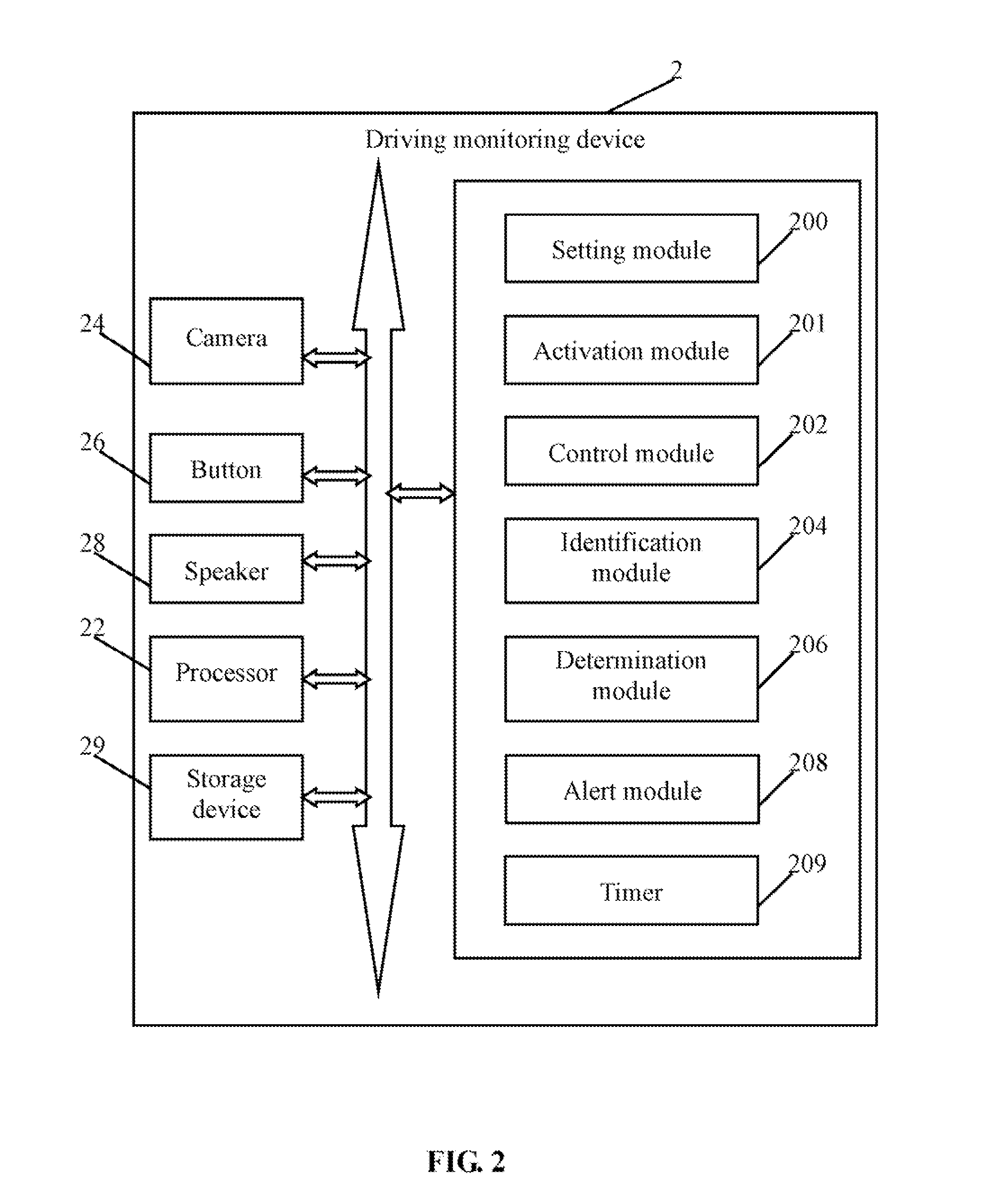
[0029]In a first embodiment, the alert module 208 outputs alert signals to prompt the driver if the driver is not awake. As mentioned above, the alert signals may be audio alert signals output by the speaker 28, such as the prerecorded sounds (e.g., “Be careful!”), a predetermined song, for example. The alert module 208 may further cut off the accelerator 4 of the vehicle 1. For example, the alert module 208 may cut off the accelerator 4 by controlling a damper brake that connects to the accelerator 4.

second embodiment

[0030]In a second embodiment, the activation module 201 invokes a second instruction if the determination module 206 determines that the driver is not awake. The second instruction may be preset by the setting module 200. The control module 202 controls the camera move to the second angle, and captures a first image of the steering wheel 3 at the second angle according to the second instruction.

[0031]The identification module 204 identifies a steering wheel region and two hand regions, divides the steering wheel region into a plurality of sub regions according to the division standard, and confirms one or more sub regions corresponding to the two hand regions. In one embodiment, the identification module 204 identifies the steering wheel region and the hand regions using a sample match method. Multiple image samples are previously stored in the storage device 29, for example, the camera 24 captures multiple images of the steering wheel 3, and multiple images of hands on different po...

third embodiment

[0035]In a third embodiment, the setting module 200 further sets a time interval to determine if the driver has adjusted a driving pose after outputting the alert signals. The timer 209 starts timing if the determination module 206 determines that the driver drives the vehicle inappropriately. The activation module 201 invokes the second instruction when the time interval has been reached.

[0036]The control module 202 controls the camera 24 to capture a second image of the steering wheel 3 at the second angle according to the second instruction. The identification module 204 identifies a steering wheel region and two hand regions in the second image, divides the steering wheel region into a plurality of sub regions according to the division standard, and confirms one or more sub regions corresponding to the hand regions.

[0037]The determination module 206 determines if the driver has adjusted the driving pose by determining if the confirmed sub regions match the standard positions. If...


PUM


Abstract

A driving monitoring device and method includes controlling a camera to capture a face image of a driver, identifying the face image to determine if the driver is awake, and controlling a camera to capture a first image of the steering wheel. The driving monitoring device and method further includes identifying a steering wheel region and two hand regions, confirming one or more sub regions of the steering wheel region corresponding to the two hand regions, determining that the driver drives the vehicle inappropriately if the confirmed sub regions do not match standard positions, and outputting alert signals to prompt the driver.

Description

BACKGROUND[0001]1. Technical Field[0002]Embodiments of the present disclosure relate to monitoring technology, and more particularly to a driving monitoring device and a method utilizing the driving monitoring device.[0003]2. Description of Related Art[0004]A driver's improper operations may result in traffic accidents, such as driver fatigue, or drunk driving. It is important to identify whether a driver is alert while driving a vehicle and give warning to the driver if they are not alert, to reduce traffic accidents.[0005]What is needed, therefore, is a driving monitoring device and a method utilizing the driving monitoring device.BRIEF DESCRIPTION OF THE DRAWINGS[0006]FIG. 1 is a block diagram of one embodiment of a vehicle including a driving monitoring device.[0007]FIG. 2 is a block diagram of one embodiment of the driving monitoring device of FIG. 1.[0008]FIG. 3 is a schematic diagram of one embodiment of a steering wheel region.[0009]FIG. 4 is a flowchart of an embodiment of ...

Claims


Application Information

Patent Timeline
Patent Type & Authority Applications(United States)
IPC IPC(8): B60Q1/00
CPCB60K28/06B60K2350/2013B60W2710/0605B60W40/09B60W2050/143B60W10/06B60K2370/21
Inventor TSAI, YING-CHUAN
Owner HON HAI PRECISION IND CO LTD
Why Eureka
Try Eureka