
Adjustable Bobber Assembly

a technology of bobbers and bobbers, which is applied in the direction of other angling devices, fishing, animal husbandry, etc., can solve the problems of not being well suited to ligh

Inactive Publication Date: 2011-06-02
SCHOLFIELD DAVID G
View PDF8 Cites 0 Cited by
  • Summary
  • Abstract
  • Description
  • Claims
  • Application Information

AI Technical Summary

Benefits of technology

[0009]According to one aspect of the present invention, a bobber is provided that can be adjustably mounted to a fishing pole to provide a visual indication of a fish striking the line on the pole. The bobber includes a main body that is attached to the fishing pole, and a pivoting indicator attached to the main body. The indicator is adjustably mounted to the main body such that the indicator can be positioned at in variety of configurations with respect to the main body to vary the amount of force required to activate the indicator. Opposite the main body the indicator is secured to a counterweight that assists in providing the balancing function of the indicator.
[0010]According to another aspect of the present invention, the indicator and optionally other suitable portions of the bobber can be formed from a luminescent material to enhance the visibility of the indicator.
[0011]According to still another aspect of the present invention, the bobber has a simple construction to facilitate construction and assembly of the bobber, and does not include any unsecured parts in the bobber assembly that could inadvertently trigger the indicator on the bobber.

Problems solved by technology

There are many tip-up and other signaling devices for ice-fishing, but these usually require a substantial force on the line to produce the signaling phenomenon, and often are not well suited for light-hitting panfish.
However, even in this configuration, the bobber employs a multitude of parts that require more involved manufacturing and assembly of the bobber than is desired.

Method used


Image

  • Adjustable Bobber Assembly
  • Adjustable Bobber Assembly
  • Adjustable Bobber Assembly

Examples


Embodiment Construction

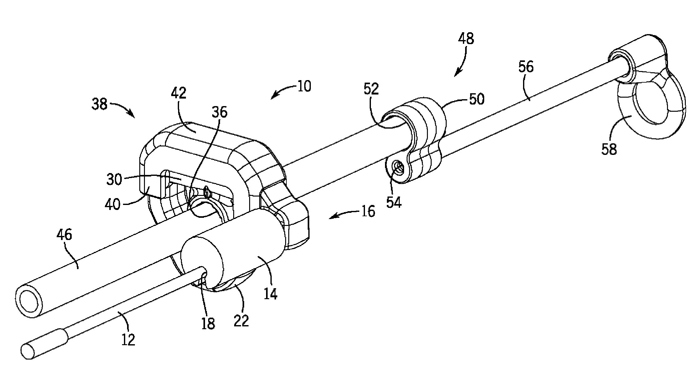
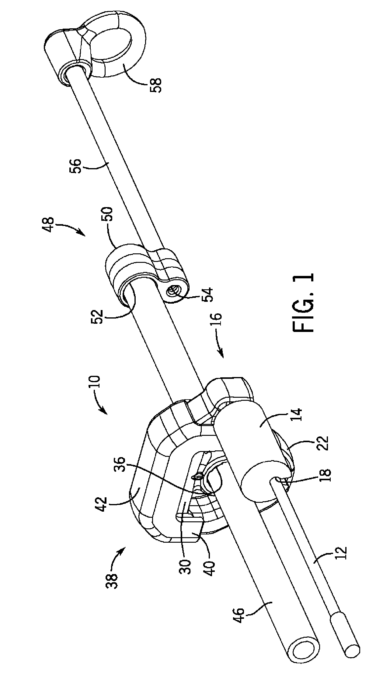
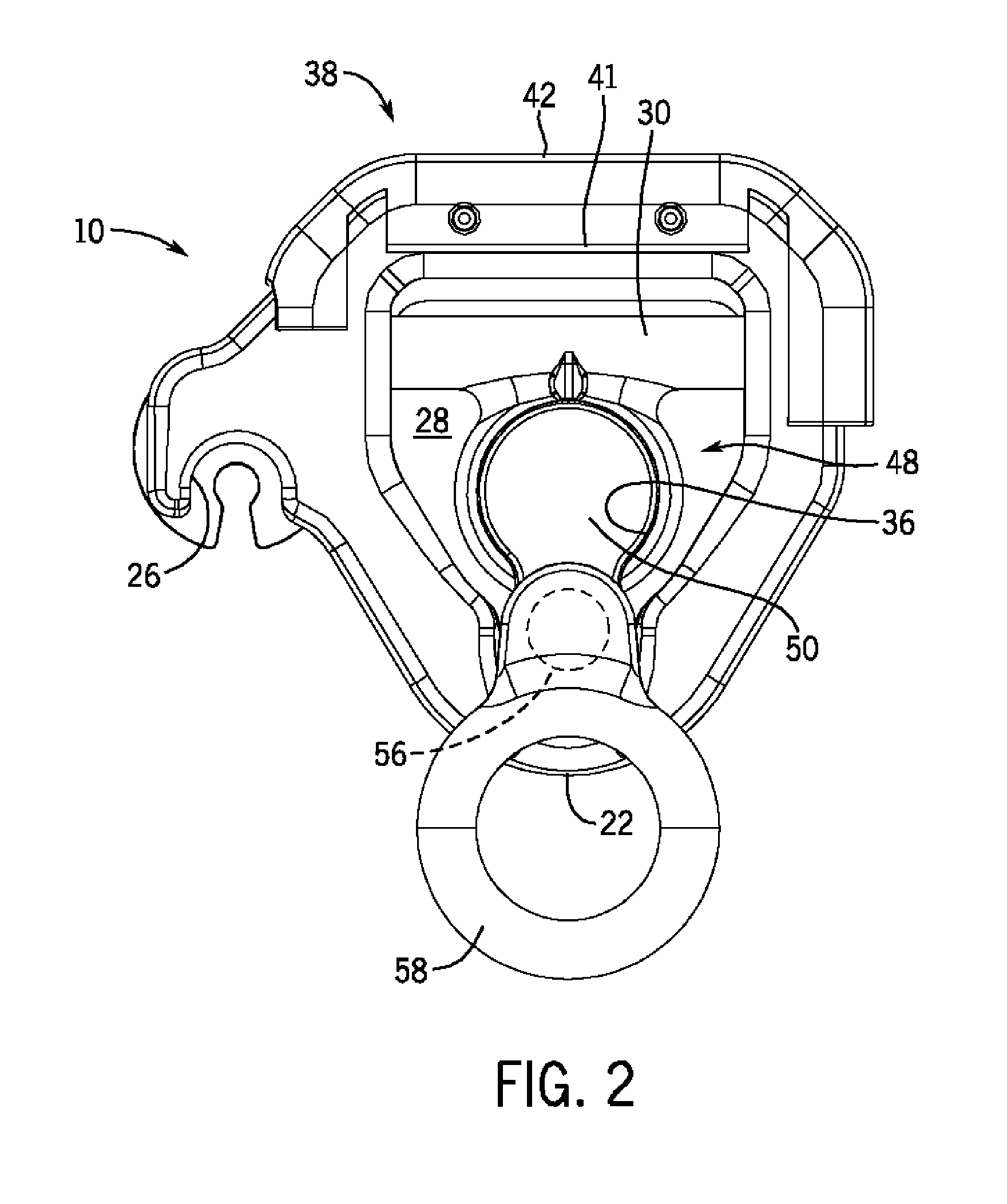
[0023]With reference now to the drawing figures in which like reference numerals designate like parts throughout the disclosure, a bobber assembly constructed according to one embodiment of the present invention is disclosed generally at 10 in FIG. 1. The bobber assembly 10 is affixed to a fishing rod 12 in either a releasable or fixed manner using a sleeve 14 positioned on a main body 16 of the assembly 10. The sleeve 14 can be formed of any suitable material, such as a plastic, silicone or rubber material, but is preferably formed of a soft rubber material to facilitate the attachment of the sleeve 14 to the rod 12. The rod 12 can be slid though a central channel 18 formed within the sleeve 14, with the passage 18 being formed with a suitable cross-sectional shape, e.g., circular or square, among others, to effectively hold the rod 12 within the sleeve 14. To assist the placement of the rod 12 within the sleeve 14, the sleeve 14 may also have a slit (not shown) formed lengthwise t...


PUM


Abstract

An adjustable bobber assembly is provided that includes a main body adapted to be secured to a fishing pole, a pivot arm pivotally secured to the main body, a locking clip secured to the main body to lock the pivot arm in place on the main body, and an indicator adjustably secured to the pivot arm and engageable with a fishing line on the fishing pole.

Description

CROSS-REFERENCE TO RELATED APPLICATIONS[0001]This application claims priority from U.S. Provisional Application Ser. No. 61 / 263,972, filed on Nov. 24, 2009, the entirety of which is expressly incorporated by reference herein.FIELD OF THE INVENTION[0002]The present invention relates generally to signaling devices for ice fishing, and in particular to adjustable balance devices for use with lures of differing weights.BACKGROUND OF THE INVENTION[0003]In ice fishing, specialized poles and rigs may be used to signal the taking of a lure by a fish. Poles are often used which rest on the ice, free of contact with the angler's hands. Some species of fish, for example perch, may exert only minute forces on the fishing line when making contact. The force of the fish tugging on the line is often so faint as to produce an imperceptible movement of the fishing pole that, when the angler does not have the rod in his hands, goes unnoticed.[0004]There are many tip-up and other signaling devices for...

Claims


Application Information

Patent Timeline
Patent Type & Authority Applications(United States)
IPC IPC(8): A01K97/01A01K93/02A01K97/12
CPCA01K97/01
Inventor SCHOLFIELD, DAVID G.
Owner SCHOLFIELD DAVID G
Learn More