Axle sleeve apparatus for optical chassis

a technology of optical chassis and sleeve, which is applied in the direction of electrical apparatus, picture communication, etc., can solve the problems of inconvenient changing and assembling of optical scanners

Active Publication Date: 2008-10-07
INTELLECTUAL VENTURES I LLC
View PDF2 Cites 0 Cited by
  • Summary
  • Abstract
  • Description
  • Claims
  • Application Information

AI Technical Summary

Benefits of technology

[0006]The main object of the present invention is to provide an axle sleeve apparatus for an optical chassis, which may provide the functions of separation from and connection with the guiding rod of a scanner to achieve the modularization of the axle sleeve apparatus for optical chassis for application and connection within guiding rod with different shapes.

Problems solved by technology

When different resolutions of scanning are needed, one also has to change the optical chassis 14 according to the aforementioned method, so it causes inconvenience for changing and assembling the optical scanner 1.

Method used


Image

  • Axle sleeve apparatus for optical chassis
  • Axle sleeve apparatus for optical chassis
  • Axle sleeve apparatus for optical chassis

Examples


Embodiment Construction

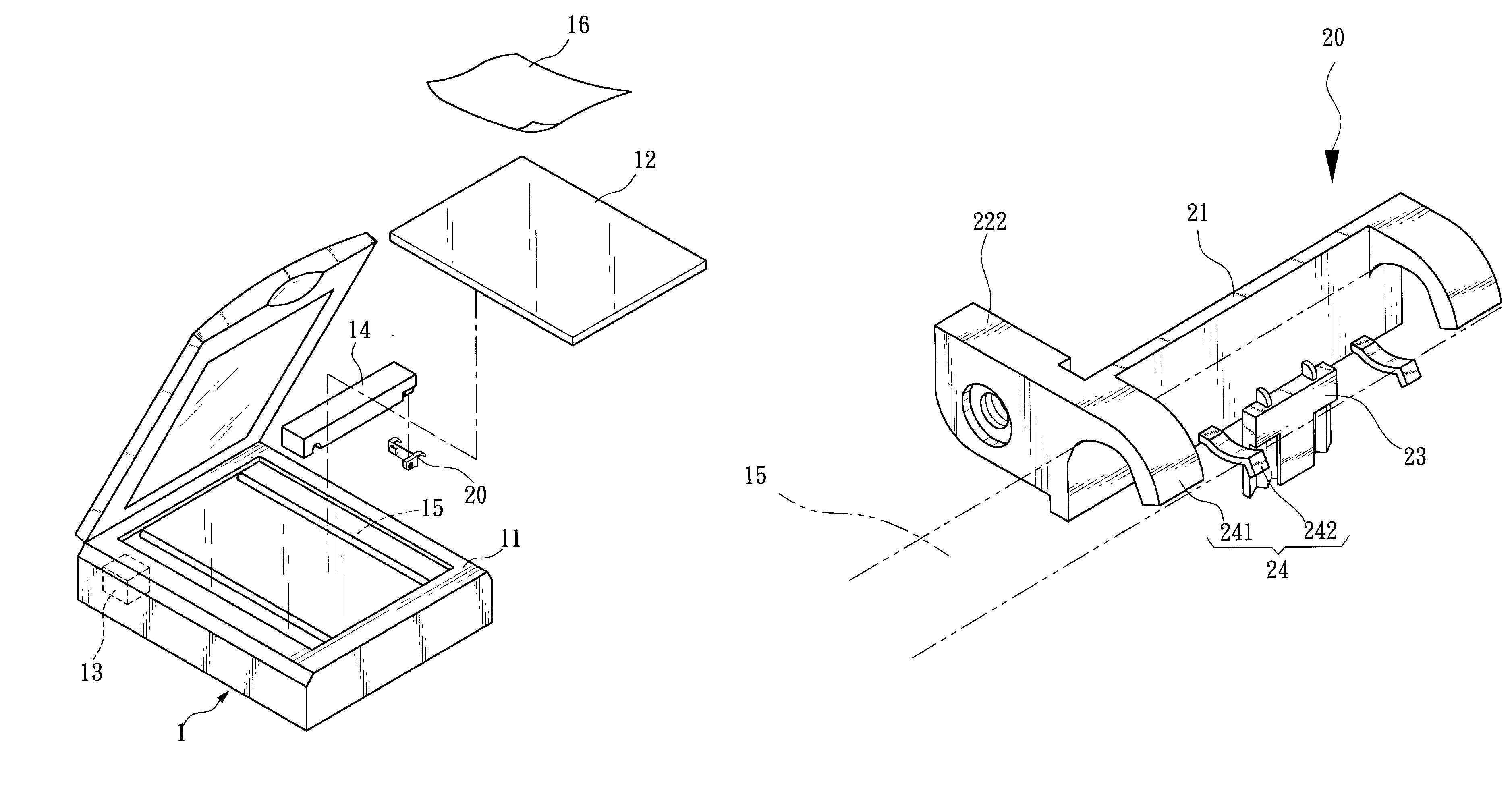
[0026]The main characteristics of the present invention is that the elastic body may choose to be located at the first position to make the axle sleeve apparatus for optical chassis connected with the guiding rod and make a linear displacement motion along the extension direction of the guiding rod, or the elastic body may choose to be located at the second position to make the axle sleeve apparatus for optical chassis separate from the guiding rod.

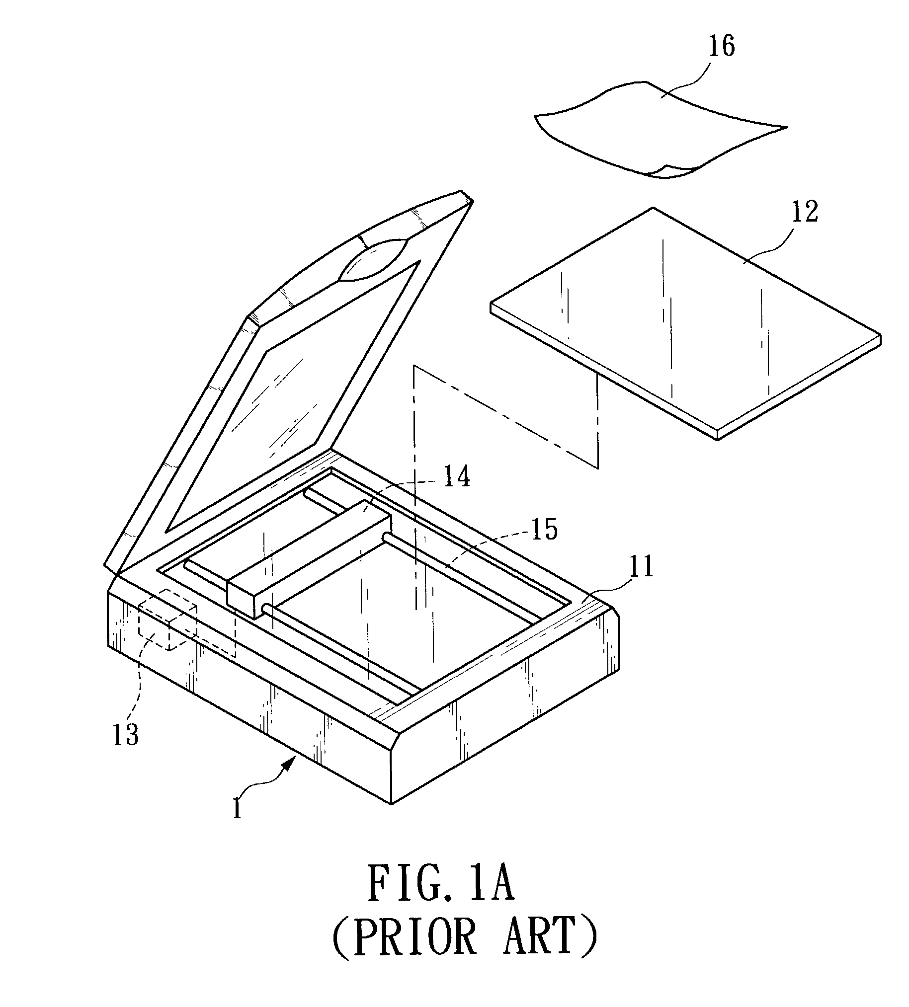
[0027]Please refer to FIG. 2A, which is a three-dimensional structural illustration for the preferable embodiment of the optical scanner according to the present invention. When the optical scanner 1 according, to the present invention executes a scanning job on a document 16 to be scanned, a document window glass 12 is arranged on the upper surface of the outer shell 11 of the optical scanner 1 for supporting the document 16 to be scanned. The optical scanner 1 is arranged with an optical chassis 14, which being guided along a guiding ro...


PUM


Abstract

The invention provides an axle sleeve apparatus for optical chassis. By the guidance of a guiding rod, the optical chassis making a linear displacement motion along the extension direction of the guiding rod. The axle sleeve apparatus for optical chassis includes an axle sleeve main body and at least one anchoring mechanism. The axle sleeve main body has a fastening mechanism capable of proceeding connection with the optical chassis. The anchoring mechanism is arranged at one side of the axle sleeve main body and capable of proceeding connection with the guiding rod. It is arranged with: a convex arm extending out one side of the axle main body and an elastic body corresponding to the convex arm. By elastic force, the elastic body may move between a first position and a second position. Wherein, the elastic body chooses to be located at the first position to make the axle sleeve apparatus for optical chassis connected with the guiding rod and make a linear displacement motion along the extension direction of the guiding rod, or the elastic body chooses to be located at the second position to make the axle sleeve apparatus for optical chassis separate from the guiding rod.

Description

FIELD OF THE INVENTION[0001]The invention relates to an axle sleeve apparatus, especially to an axle sleeve apparatus for optical chassis that is being connected with or separated from the guiding rod of a scanner.BACKGROUND OF THE INVENTION[0002]Recently, since the abrupt progress of high technology, especially the relative field of the manufacture of the micro-electronic technology further changes day by day, so the computer has already penetrated into each family and business and become a necessary and indispensable electronic product. Following the prevalence of multi-media of computers, more peripheral products are needed as devices for input and output. Since the continuous innovation for the optical semi-conductor technology, so the product technology of the relative peripheral equipment of computers such as optical scanners becomes more matured day by day, and the optical scanner is more and more popular as a necessary product in the computer's peripheral equipment.[0003]Ple...

Claims


Application Information

Patent Timeline
Patent Type & Authority Patents(United States)
IPC IPC(8): H04N1/04H04N1/10H04N1/193
CPCH04N1/1017H04N1/193H04N2201/0442
Inventor HUANG, YIN-CHUNYEH, CHIEN-LIANG
Owner INTELLECTUAL VENTURES I LLC
Why Eureka
Try Eureka