Microstructures For Fluidic Ballasting and Flow Control

a microstructure and fluidic ballasting technology, applied in the field of micro- and nano-scale fluidic systems, can solve the problem that micro-scale fluidic systems cannot achieve the important performance advantages

Inactive Publication Date: 2011-06-02
MASSACHUSETTS INST OF TECH
View PDF13 Cites 74 Cited by
  • Summary
  • Abstract
  • Description
  • Claims
  • Application Information

AI Technical Summary

Benefits of technology

[0011]This ballast can be configured in a fluidic element array including a plurality of fluidic elements where each element includes an input port and an output port through which a prespecified output flow rate is required. A reservoir is connected for delivery of a fluid from the reservoir to each fluidic element input port. An hydraulic ballast structure is provided for each fluidic ele...

Problems solved by technology

Without device-specific, microscale fluidic flow control, microscale fluidic systems ...

Method used


Image

  • Microstructures For Fluidic Ballasting and Flow Control
  • Microstructures For Fluidic Ballasting and Flow Control
  • Microstructures For Fluidic Ballasting and Flow Control

Examples


Embodiment Construction

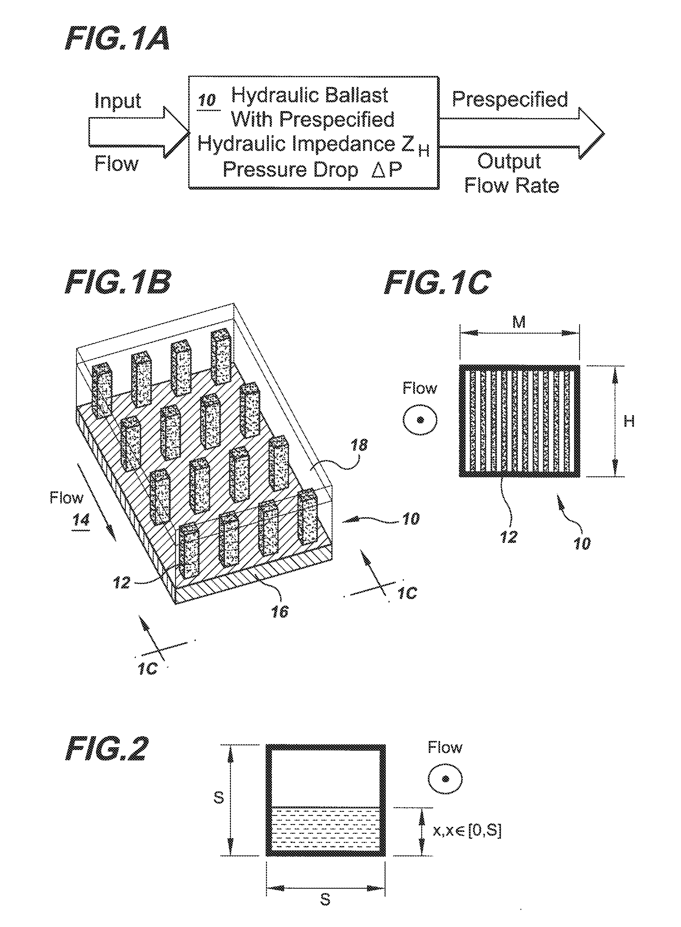
[0029]Referring to FIG. 1A, there is schematically represented the operation of the hydraulic ballast of the invention. The hydraulic ballast 10 is designed, in the manner described below, to provide a prespecified hydraulic impedance, ZH, and a prespecified pressure drop, ΔP. An input of fluid or gas flows through the hydraulic ballast and experiences the prespecified pressure drop of the ballast. This pressure drop in the flow results in the production of a prespecified flow rate out of the ballast. The hydraulic ballast thereby imposes a prespecified pressure drop on the input flow for a corresponding prespecified output flow rate. As explained in detail below, this ballasting configuration of the invention can be implemented for a single hydraulic element or can be implemented for each element in an array of elements, with the ballasting configuration customized to produce the output flow rate required for each element.

[0030]Also referring to FIGS. 1B-1C, there is schematically ...


PUM


Abstract

In one example hydraulic ballast of the invention there is provided an input port and an output port through which a prespecified output flow rate is required. There is provided between the input and output ports a ballasting array of columns having a cross-sectional column extent, W, a column pitch, P, and an array length, L, selected based on the required output flow rate, to produce a prespecified pressure drop that enforces the required output flow rate.

Description

CROSS-REFERENCE TO RELATED APPLICATION[0001]This application claims the benefit of U.S. Provisional Application No. 60 / 964,827, filed Aug. 15, 2007, the entirety of which is hereby incorporated by reference.STATEMENT REGARDING FEDERALLY SPONSORED RESEARCH[0002]This invention was made with Government support under Contract No. W911QY-05-1-0002 awarded by DARPA. The Government has certain rights in the invention.BACKGROUND OF INVENTION[0003]This invention relates generally to microscale and nanoscale fluidic systems, and more particularly relates to flow control in microscale and nanoscale fluidic systems.[0004]There is a wide range of fluidic systems for which scaling down of system features to the microscale provides important advantages. For example, chemical reactors, which bring together reactants that produce a chemical reaction, benefit from scaling down of chemical injectors and reactor packed beds to the microscale because the surface area per unit reaction volume increases a...

Claims


Application Information

Patent Timeline
IPC IPC(8): F03B15/00
CPCB01L3/0268B01L2400/027Y02E60/50B05B5/0255H01M8/04201B01L2400/086Y10T137/8593
Inventor VELASQUEZ-GARCIA, LUIS F.AKINWANDE, AKINTUNDE I.
Owner MASSACHUSETTS INST OF TECH
Why Eureka
Try Eureka