Blind device for light protection and displaying of information

a technology of light protection and information, applied in the field of blind devices, can solve the problems of not having the purpose of fixed devices, not allowing a corresponding adjustment to different angles of sun radiation and intensity, and previous embodiments of light sources in shade arrangements cannot be used and adjusted like blinds, so as to achieve full transparency for the viewer and strong linearity

Inactive Publication Date: 2011-06-02
YORDANOVA MARIANA
View PDF13 Cites 40 Cited by
  • Summary
  • Abstract
  • Description
  • Claims
  • Application Information

AI Technical Summary

Benefits of technology

[0057]The blind device preferably has means for rotatably attaching the slat to an object, in particular, for a rotation of the slat around a longitudinal axis of the slat. The blind / sun protection element (i.e. the slat) has a shape that has a stronger pronounced linearity in the longitudinal axis. The narrow end of the blind / sun protection element can be designed differently as regards geometry: oval, concavely, convexly, straightly or wave-like. Further, the blind device comprises means for linearly moveable arrangement of the slats to an object, i.e. the slats are capable to be elevated up and down or from the left to the right in respect to the object. The light sources according to the present invention are arranged so that the movement of the slats are not hindered.
[0058]A preferred advantage of the blind device according to the present invention is that the drive up of the blinds occurs simultaneously with the one or more integrated light sources. The operation of the blind device is similar to the operation of a usual sun protection blind.
[0059]A further preferred advantage is that when piling up the light sources integrated in the blind / sun protection elements can be arranged close on top of each other and therefore allow a free sight and full transparency for the viewer. The invention allows a flexible use on the building front and is no obstacle as previous display and light arrangements have been.

Problems solved by technology

All these systems have fixed devices which do not have the purpose of fulfilling a sun light protection function and do not allow a corresponding adjustability to different angle of sun radiation and intensity.
Previous embodiments of light sources in shade arrangements cannot, however, at the same time be used and adjusted like a blind.
In order to add the display function to a blind device, the whole blind device need to be replaced, or both need to be installed separately, which is inflexible, may cause high cost, is inconvenient for the installation.

Method used


Image

  • Blind device  for light protection and displaying of information
  • Blind device  for light protection and displaying of information
  • Blind device  for light protection and displaying of information

Examples


Embodiment Construction

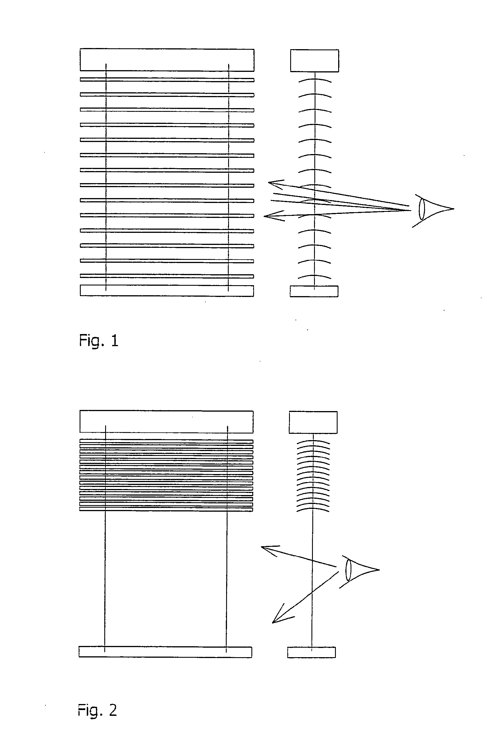
[0076]FIG. 1 and FIG. 2 show a conventional sun protection arrangement consisting of sever 11 slats only having the function of sun protection.

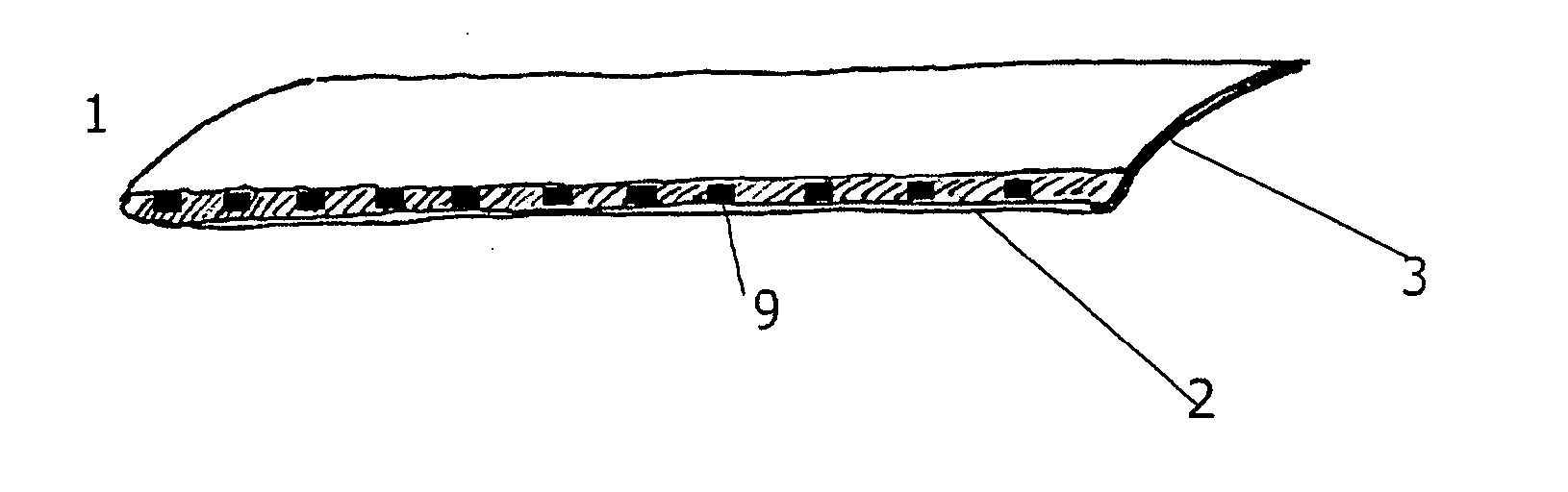
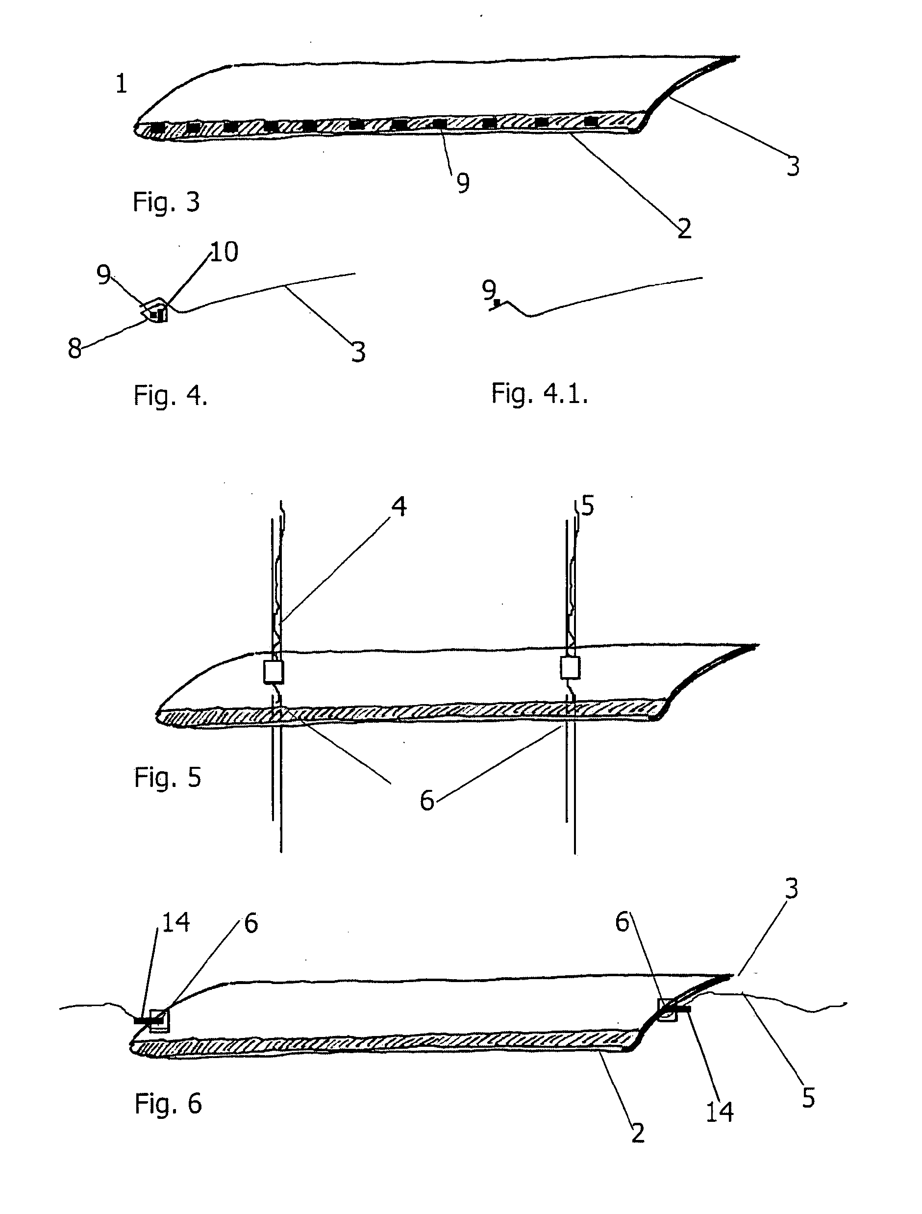
[0077]FIG. 3 shows a blind device 1 comprised of a light protection slat 3 and a light and display arrangement 2. Each light and display arrangement 2 comprises one or more light sources coupled optically to the light protection element 3.

[0078]FIG. 4 shows an embodiment in which the light sources 9 are arranged at a separately designed light source carrier 10 surrounded by a housing, wherein the housing may be optional.

[0079]FIG. 4.1 shows an embodiment in which the light or sunlight protection element 3 may be the light source carrier 10. In this case no light source carrier 10 has to be arranged if the light protection element 3 per se has the material properties to serve as such. Furthermore, the light protection element 3 can be designed such that its natural properties are upgraded by coating, applying patterns, making holes or deformat...


PUM


Abstract

The present invention relates to a blind device for controllable light protection and/or displaying of information, said device comprising: at least one slat being moveably arranged, at least one light source attached to said slat, a guide cord being adapted to hold the slat in the blind device and/or to rotate said slat, a lifting strip being adapted to elevate the slat within said blind device and a wire for providing electrical connection, wherein said wire is guided through the slat and/or along the guide cord and/or the lifting strip.

Description

TECHNICAL FIELD[0001]The invention relates to a blind device, particularly a Venetian blind device, comprising at least one slat for light protection, an arrangement comprising at least one of the blind devices and a method for light protection and for the display of information.TECHNICAL BACKGROUND[0002]Regarding the illumination of buildings, devices are known which mostly have one or more immobile carrier systems which are connected to one or more light sources and serve for illuminating the building from the outside. Simultaneously, also display devices are known which serve to display information and are designed as a board or table or as several boards or tables arranged next to each other. Display devices that have different transparencies are also known from EP-A-1-293-955. All these systems have fixed devices which do not have the purpose of fulfilling a sun light protection function and do not allow a corresponding adjustability to different angle of sun radiation and inte...

Claims


Application Information

Patent Timeline
Patent Type & Authority Applications(United States)
IPC IPC(8): E06B9/36E06B9/386F21V33/00
CPCE06B9/326E06B2009/247E06B9/386H02S20/30Y02E10/50
Inventor YORDANOVA, MARIANA
Owner YORDANOVA MARIANA
Why Eureka
Try Eureka