Ion generating unit and lighting apparatus

a technology of generating unit and lighting apparatus, which is applied in the direction of instruments, heating types, corona discharge, etc., can solve the problems of inability to achieve sufficient cleaning effect in locations within the room, inability to provide sufficient cleaning effect to an entire working space or accommodation space, and inability to achieve sufficient removal effect against harmful floating particles, etc., to achieve the effect of reducing the number of replacing ion generators or light sources, prolonging the product life and reducing the number of replacemen

Inactive Publication Date: 2011-06-02
SHARP KK
View PDF5 Cites 8 Cited by
  • Summary
  • Abstract
  • Description
  • Claims
  • Application Information

AI Technical Summary

Benefits of technology

[0026]In the present invention, the LED is used as the light source. The LED has a long product life, and by driving the ion generators according to the above described invention, a product life of the ion generators can be elongated; thus the number of replacing the ion generators or the light source can be reduced, and a trouble of the user can be saved.
[0027]According to the present invention, the ion concentration in the space can quickly be raised to the predetermined concentration upon start up, and the elongation of a product life of the ion generators can be achieved while maintaining the predetermined ion concentration.

Problems solved by technology

In an apparatus using such a filter, it is difficult to provide a cleaning effect to an entirety of the working space or accommodation space.
For example, a sufficient cleaning effect cannot be expected in locations within a room where air tends to stagnate, such as behind a furniture arranged within a room and corners of the room.
Further, there has been a problem that a sufficient removing effect cannot be achieved against harmful floating particles such as germs, viruses.
However, the high pressure ozone generating Japanese Patent Application Laid-Open No. 2001-19409 is configured such that a voltage is applied alternately to the electric discharge electrode pairs of the plurality of blocks to discharge the electricity, and then to generate the ozone, thus, compared to a case in which both of the electric discharge electrode pairs are used, there was a problem that upon start up of the apparatus, a long time is required until the ozone is filled in a space and reaches a predetermined concentration.

Method used


Image

  • Ion generating unit and lighting apparatus
  • Ion generating unit and lighting apparatus
  • Ion generating unit and lighting apparatus

Examples


Embodiment Construction

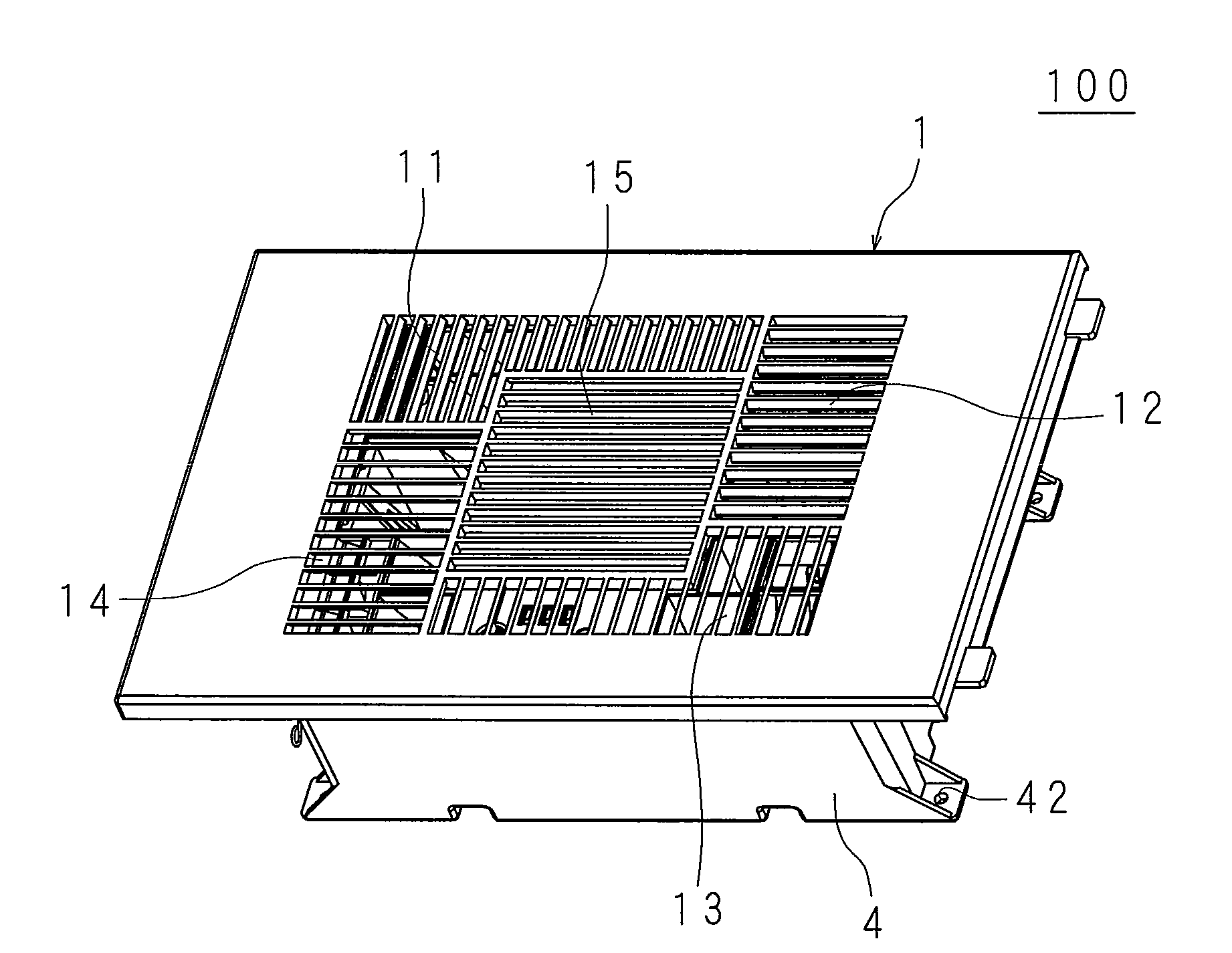
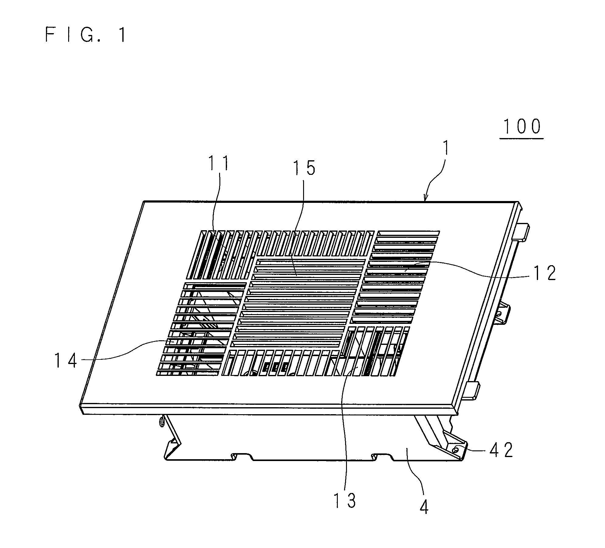
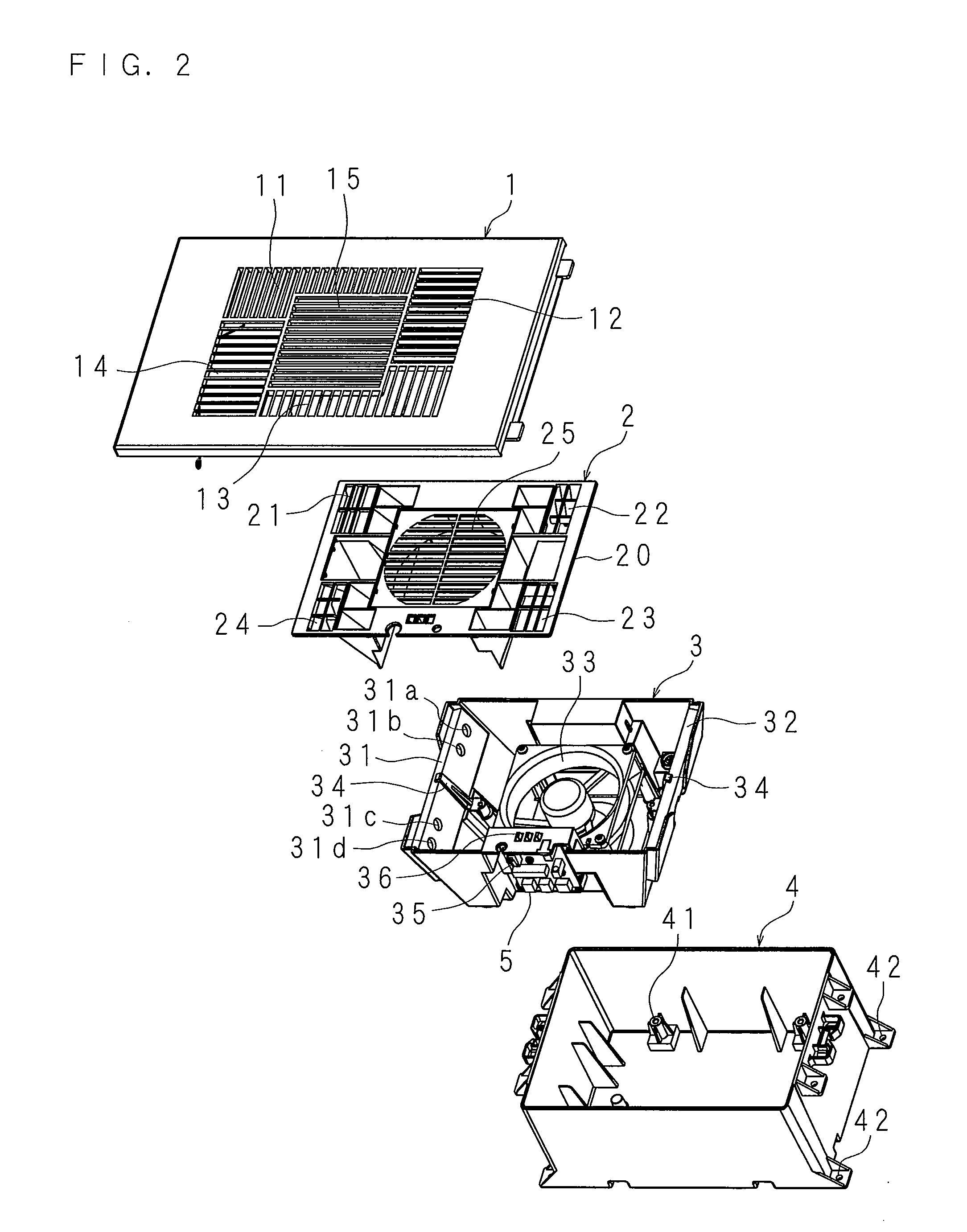
[0050]Hereinbelow, the present invention will be described in detail with reference to the drawings showing embodiments thereof, using an example of an air cleaning unit provided with a fan for ventilating ions generated in ion generators serving as an ion generating unit. FIG. 1 is an external perspective view of an ion generating unit 100 of the present invention. FIG. 2 is an exploded perspective view of the ion generating unit 100. FIG. 3 is an exploded perspective view of a primary part of the ion generating unit 100. FIG. 4 is an exploded perspective view of the ion generating unit 100 seen from a rear side. It should be noted that in the description of the embodiments, a “front side” refers to a face on a side where an air outlet from which the ion containing air is blown out is provided, and a “rear side” refers to a face that is opposite the front side.

[0051]The ion generating unit 100 includes a substantially cuboid casing 4, a main body base 3 that is attached to an insid...


PUM


Abstract

In an ion generating unit configured to control driving of a plurality of ion generating elements for generating ions by a controller, the controller drives the ion generating elements upon start up, and is configured to keep driving for a predetermined time period; thereby, the ion concentration of a space upon start up is quickly raised to a predetermined concentration. Further, the controller is configured to drive the ion generating elements intermittently and one after another in order after the predetermined time period has elapsed; the product life is elongated while maintaining the predetermined ion concentration and shortening the driving time of the ion generating elements.

Description

[0001]This application is the national phase under 35 U.S.C. §371 of PCT International Application No. PCT / JP2009 / 003454 which has an International filing date of Jul. 23, 2009 and designated the United States of America.TECHNICAL FIELD[0002]The present invention relates to an ion generating unit that generates ions by driving ion generator, and a lighting apparatus provided with the ion generating unit.DESCRIPTION OF RELATED ART[0003]In recent years, as a sealing property of internal spaces of buildings such as factories, offices and houses is improved, with an aim to realize a clean and comfortable working space or accommodation space, a desire to clean air by removing floating particles that are harmful to human body is ever growing. As a technique for such an air cleaning, conventionally, a technique of taking air within a target space, letting the air pass through a filter, and removing the floating particles by catching them with the filter had been widely adapted.[0004]In an ...

Claims


Application Information

Patent Timeline
Patent Type & Authority Applications(United States)
IPC IPC(8): F21V33/00H01J27/00
CPCA61L9/22H01T23/00F24F2003/1682F24F8/30
Inventor KAMII, MIWAKATAOKA, YASUTAKA
Owner SHARP KK
Why Eureka
Try Eureka