Image forming apparatus for preventing abnormally discharged image

a technology of image forming apparatus and discharged image, which is applied in the direction of electrographic process apparatus, corona discharge, instruments, etc., can solve the problems of reduced product life of photosensitive drum, increased abrasion, and non-uniform surface potential of photosensitive drum when exposed by exposing apparatus such as lasers, and achieves the effect of prolonging product li

Active Publication Date: 2017-10-24
CANON KK
View PDF19 Cites 0 Cited by
  • Summary
  • Abstract
  • Description
  • Claims
  • Application Information

AI Technical Summary

Benefits of technology

[0010]An object of the present invention is to provide an image forming apparatus capable of realizing longer product life while avoiding an occurrence of an abnormally discharged image.
[0050]when an image formation operation is executed after the second exposing unit exposes the photosensitive member, the second adjusting portion adjusts an amount of exposure light based on a value of a current detected by the current detecting portion so that a current value of a current flowing through the charging member has a magnitude that prevents a region of the photosensitive member charged by the charging member after being exposed by the second exposing unit from entering an overcharged state.

Problems solved by technology

As a result, the surface of the photosensitive drum sustains damage, an amount of abrasion increases, and product life of the photosensitive drum is reduced.
However, charging a photosensitive drum particularly using a DC system creates the following problems.
As a result, surface potential of the photosensitive drum when exposed by an exposing apparatus such as a laser may also become nonuniform.
In addition, while suppressing ghost images, since pre-charge exposure also lowers surface potential of the photosensitive drum prior to charge, an amount of discharge increases and, as a result, an amount of abrasion of the photosensitive drum increases.
However, Japanese Patent Application Laid-open No. 2009-42738 describes that an overcharge (abnormal discharge) of charged potential sometimes occurs when charging a region after irradiation for preliminary exposure to create a mesh-like abnormally discharged image.

Method used


Image

  • Image forming apparatus for preventing abnormally discharged image
  • Image forming apparatus for preventing abnormally discharged image
  • Image forming apparatus for preventing abnormally discharged image

Examples


first practical example

[0069]

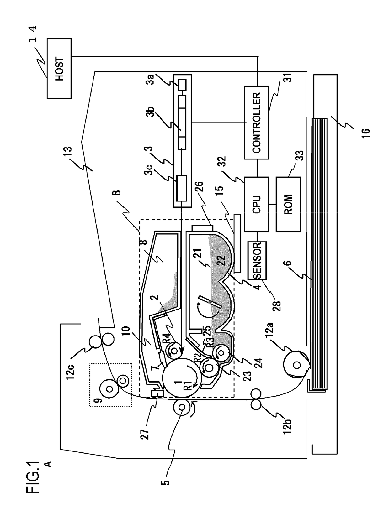
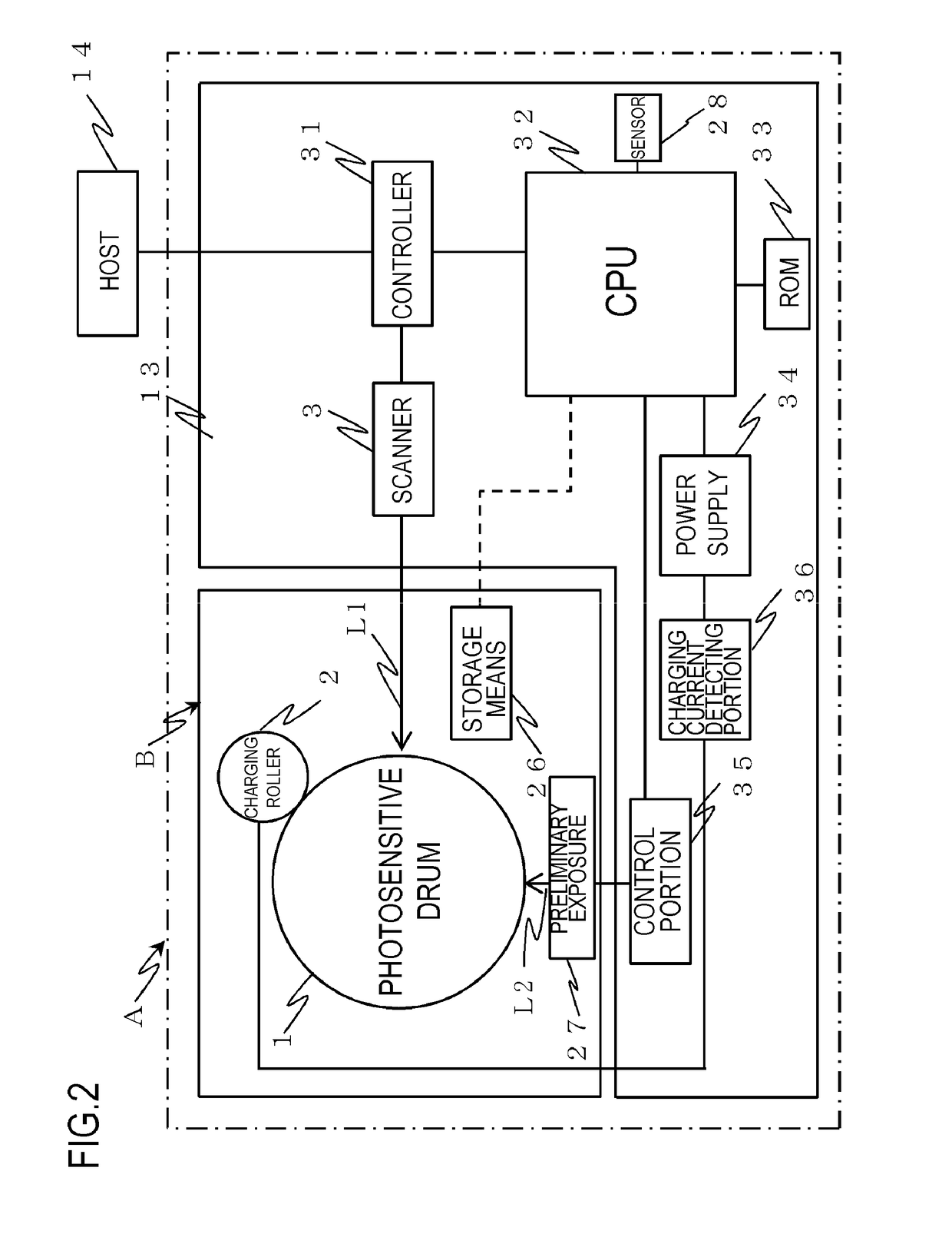
[0070]A schematic configuration of an image forming apparatus according to a practical example of the present invention will be described with reference to FIGS. 1 and 2. FIG. 1 is a schematic sectional view showing a schematic configuration of an image forming apparatus according to a practical example of the present invention. FIG. 2 is a control block diagram of an image forming apparatus according to a practical example of the present invention. Examples of an image forming apparatus A according to the present practical example includes a laser beam printer which forms an image on, for example, a recording medium (recording material) 6 that is a sheet of recording paper, an OHP sheet, or the like with an electrophotographic system in accordance with image information. In addition, as will be described in detail later, with the image forming apparatus A according to the present practical example, a process cartridge B is configured to be attachable and detachable to and fro...

second practical example

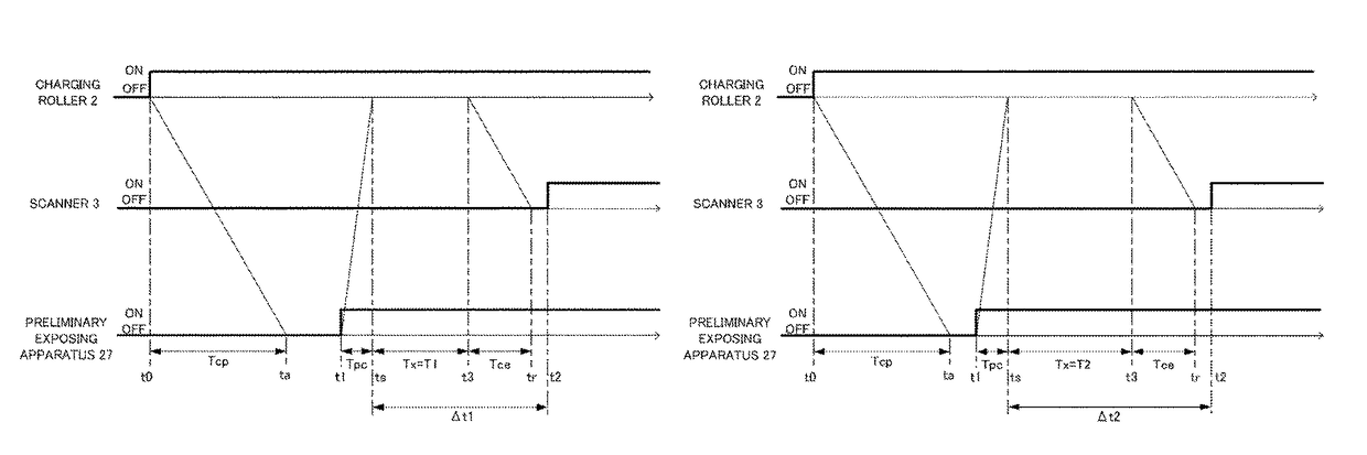
[0123]An abnormal discharge period depends on a resistance value of the charging roller 2. As described earlier, the lower the resistance value of the charging roller 2, the longer the abnormal discharge period, and the higher the resistance value of the charging roller 2, the shorter the abnormal discharge period. In consideration thereof, in a second practical example of the present invention, an abnormal discharge period is calculated based on information related to a charging capability of the charging roller 2 in addition to information related to the film thickness of the photosensitive drum 1 and information related to the use environment. Otherwise, the second practical example is the same as the first practical example and, accordingly, a description of configurations of the second practical example that are similar to those of the first practical example will be omitted.

[0124]The charging capability of the charging roller 2 is correlated to the resistance value of the char...

third practical example

[0128]In a third practical example of the present invention, a charging current flowing through the charging roller 2 is measured and the period between the start of irradiation by the preliminary exposing apparatus 27 and the start of image exposure by the scanner 3 is varied based on a period in which the measured current value exceeds a prescribed range. In the third practical example, descriptions of configurations in common with those of the first and second practical examples will be omitted. Matters not described in the third practical example are similar to those described in the first and second practical examples.

[0129]

[0130]In the present practical example, a charging current flowing through the charging roller 2 is measured and an abnormal discharge period is calculated (acquired) based on the measured charging current value. In order to measure a charging current flowing through the charging roller 2, as shown in FIG. 2, the present practical example includes a charging...


PUM


Abstract

An image forming apparatus includes: a first exposing unit exposing a surface of a charged photosensitive member to form a latent image; a second exposing unit exposing the surface of the photosensitive member after the surface of the photosensitive member passes a transfer position at which a toner image obtained by causing toner to adhere to the latent image is transferred to a transferred body and before the surface of the photosensitive member reaches a charging position; and a control unit varying a length of a period from a timing at which a portion of the photosensitive member exposed by the second exposing unit is initially charged by the charging member to a timing at which the first exposing unit starts formation of the latent image when performing image formation based on a print signal, based on information related to a photosensitive layer thickness of the photosensitive member.

Description

BACKGROUND OF THE INVENTION[0001]Field of the Invention[0002]The present invention relates to an image forming apparatus which forms an image on recording material using an electrophotographic system.[0003]Description of the Related Art[0004]Examples of conventional image forming apparatuses using an electrophotographic system include an electrophotographic copier, an electrophotographic printer (such as an LED printer and a laser beam printer), and an electrophotographic facsimile device. In an image forming apparatus of this type, a surface of an electrophotographic photosensitive member (hereinafter, referred to as a photosensitive drum or a drum) is uniformly charged by a primary charger and the charged photosensitive drum surface is exposed by an exposing apparatus to form an electrostatic latent image. The electrostatic latent image is then developed by a developing apparatus to form a developer image (hereinafter, referred to as a toner image) and the toner image is transferr...

Claims


Application Information

Patent Timeline
Patent Type & Authority Patents(United States)
IPC IPC(8): G03G15/00G03G15/02G03G21/08
CPCG03G15/0266G03G21/08G03G15/553G03G15/5033
Inventor AGATA, SHINICHIIKADA, KOSUKE
Owner CANON KK
Why Eureka
Try Eureka