Process for manufacturing a plastic fuel tank equipped with a pump
- Summary
- Abstract
- Description
- Claims
- Application Information
AI Technical Summary
Benefits of technology
Problems solved by technology
Method used
Image
Examples
Embodiment Construction
, reference will now be made to the accompanying drawings in which:
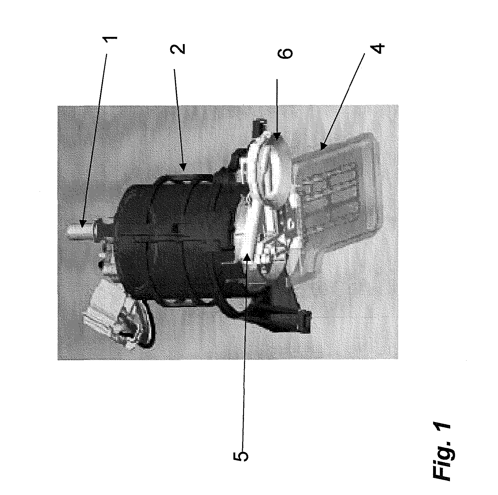
[0021]FIG. 1 illustrates a pump located in an intermediate part;
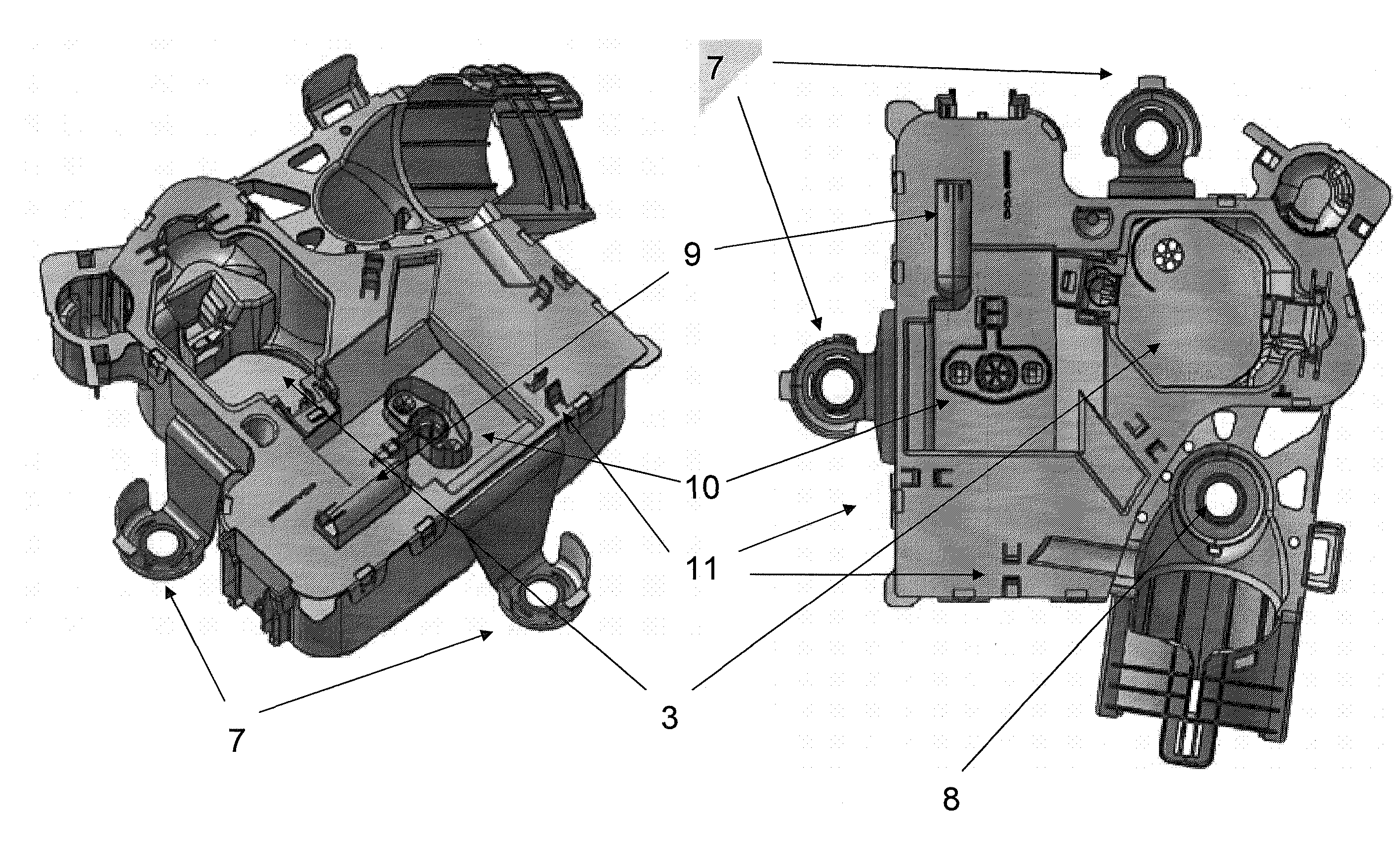
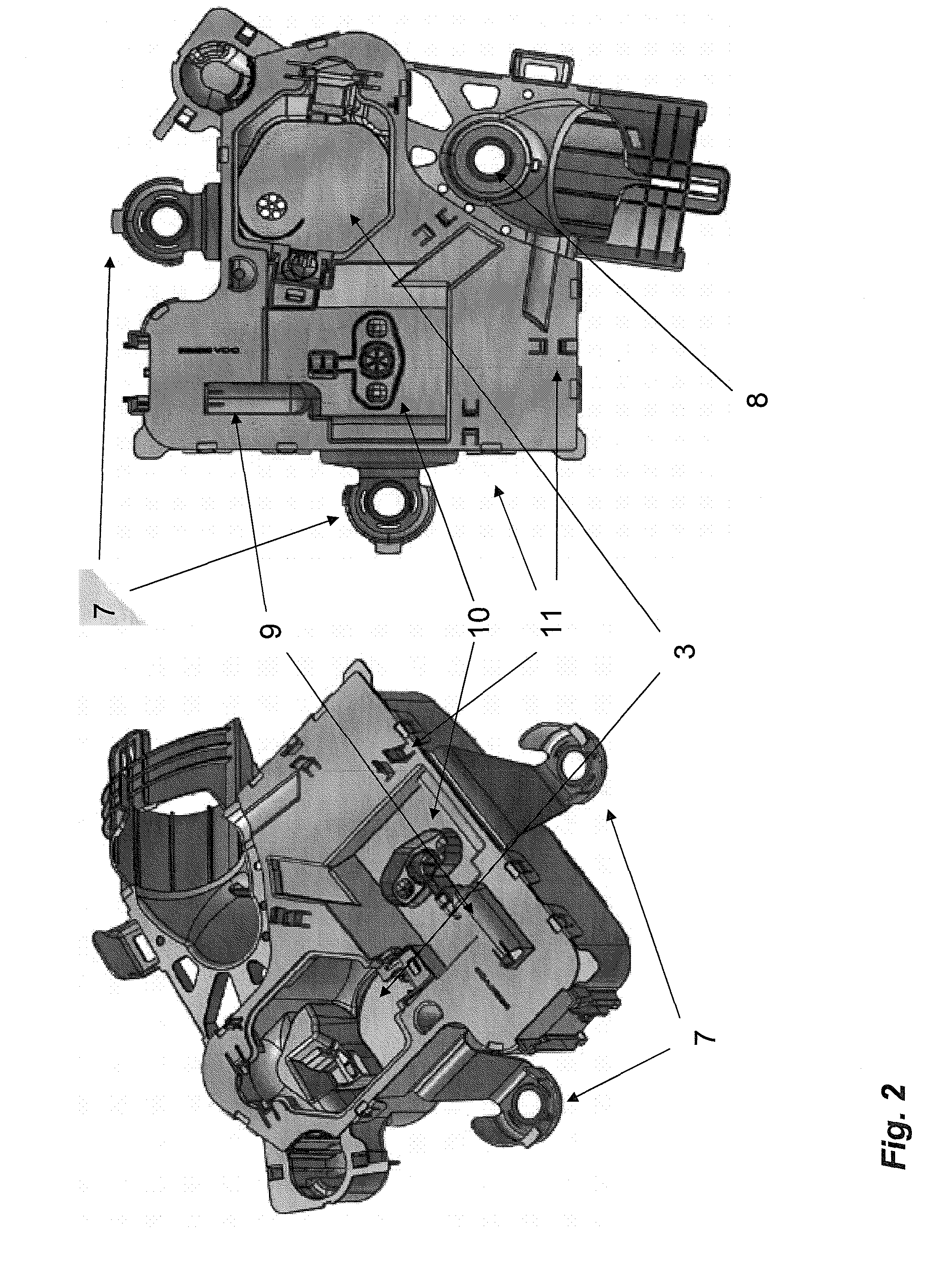
[0022]FIG. 2 illustrates a swirl pot with a housing which is intended for the pump and the intermediate part from FIG. 1;
[0023]FIG. 3 shows details of certain devices present on the cover of the swirl pot, namely: a relief (9), a relief (10), and clips (11) in three separate views;
[0024]FIG. 4 illustrates the intermediate part in detail in two different views comprising a pump holder (2′) and a separate cover (2″) to provide leaktightness to the swirl pot; and
[0025]FIG. 5 illustrate an advantageous way of ensuring that the pump can move relative to at least one of is points of attachment to the wall of the tank.
DESCRIPTION OF THE PREFERRED EMBODIMENTS
[0026]According to one preferred variant, this intermediate part may be provided with flexible support(s) whose role is to absorb the vibrations of the pump and, in doing so, reduce the acoustic emissions. A...
PUM
| Property | Measurement | Unit |
|---|---|---|
| Volume | aaaaa | aaaaa |
| Volume | aaaaa | aaaaa |
| Flexibility | aaaaa | aaaaa |
Abstract
Description
Claims
Application Information
 - R&D
- Intellectual Property
- Life Sciences
- Materials
- Tech Scout
- Unparalleled Data Quality
- Higher Quality Content
- 60% Fewer Hallucinations
Browse by: Latest US Patents, China's latest patents, Technical Efficacy Thesaurus, Application Domain, Technology Topic, Popular Technical Reports.
© 2025 PatSnap. All rights reserved.Legal|Privacy policy|Modern Slavery Act Transparency Statement|Sitemap|About US| Contact US: help@patsnap.com


