Demand based wrapping

a demand-based wrapping and load technology, applied in the directions of wrapping, packaging, transportation and packaging, etc., can solve the problems of excess packaging material supply, loosely wrapped loads, packaging material breakage,

Active Publication Date: 2011-06-09
LANTECH COM
View PDF96 Cites 100 Cited by
  • Summary
  • Abstract
  • Description
  • Claims
  • Application Information

AI Technical Summary

Benefits of technology

[0010]According to an aspect of the present disclosure, a control system for a wrapping apparatus may include a packaging material dispenser configured to dispense packaging material for wrapping a load. The control system may also include at least one sensor assembly configured to generate a signal based on instantaneous demand for packaging material at the load. The control system may further include a controller configured to control operation of the packaging material dispenser based at least in part on the signal.

Problems solved by technology

Historically, wrappers have suffered from packaging material breaks and limitations on the amount of wrap force applied to the load (as determined in part by the amount of pre-stretch used) due to erratic speed changes required to wrap “non-square” loads, such as narrow, tall loads, short, wide loads, and short, narrow loads.
The non-square shape of such loads often results in the supply of excess packaging material during the wrapping cycle, during time periods in which the demand rate for packaging material by the load is exceeded by the supply rate of the packaging material by the packaging material dispenser.
This leads to loosely wrapped loads.
In addition, when the demand rate for packaging material by the load is greater than the supply rate of the packaging material by the packaging material dispenser, breakage of the packaging material may occur.
Variations in demand may make it difficult to properly wrap the load.
The problem with variations is exacerbated when wrapping a load having one or more dimensions that may differ from one or more corresponding dimensions of a preceding load.
The problem may also be exacerbated when wrapping a load having one or more dimensions that vary at one or more locations of the load itself.
With the ever faster wrapping rates demanded by the industry, the rotation speeds have increased significantly to a point where the concept of sensing changes in force and altering supply speed in response loses effectiveness.
Use of high speed wrapping has therefore been limited to relatively lower wrap forces and pre-stretch levels where the loss of control at high speeds does not produce undesirable packaging material breaks.

Method used


Image

  • Demand based wrapping
  • Demand based wrapping
  • Demand based wrapping

Examples


Embodiment Construction

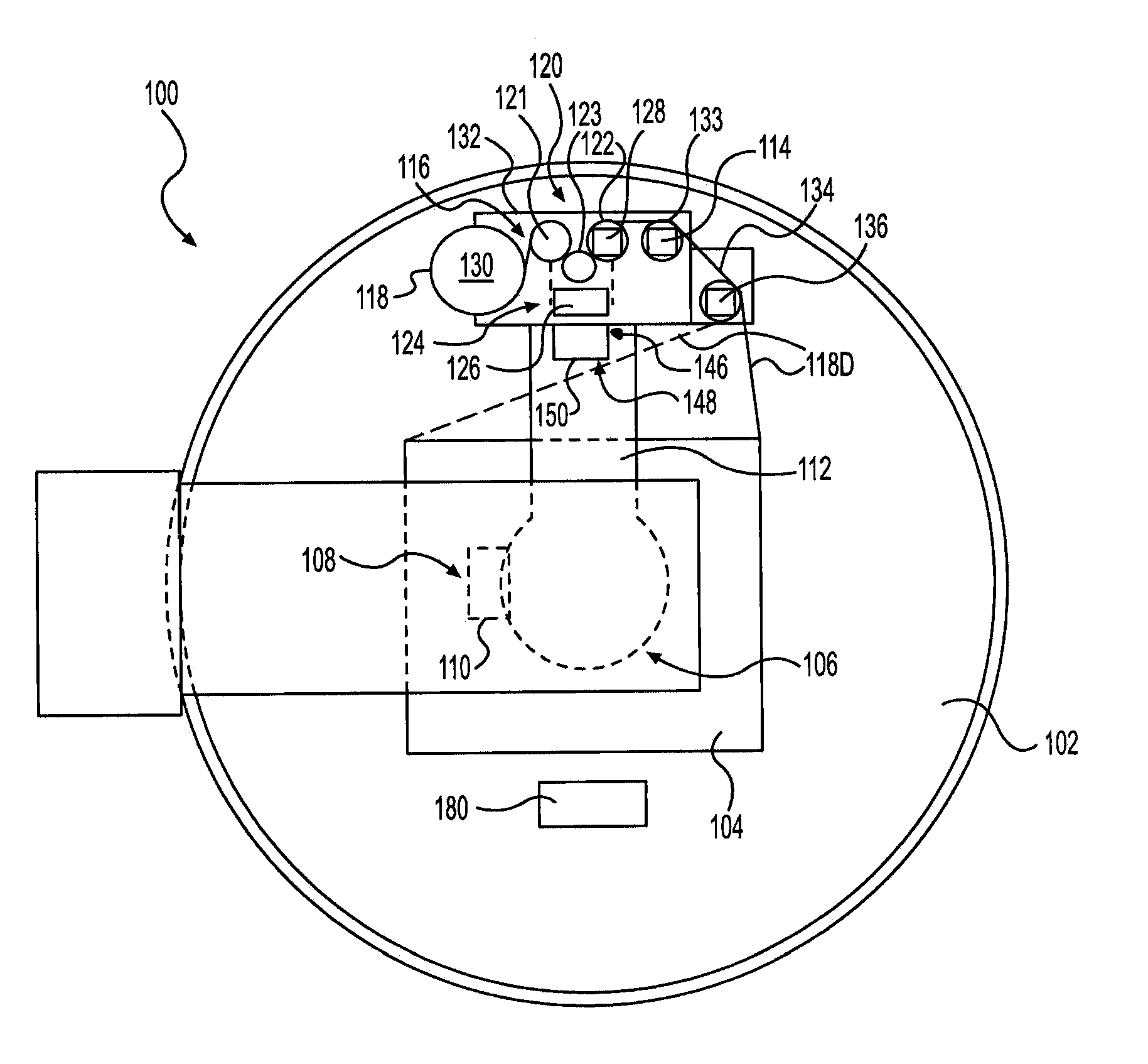
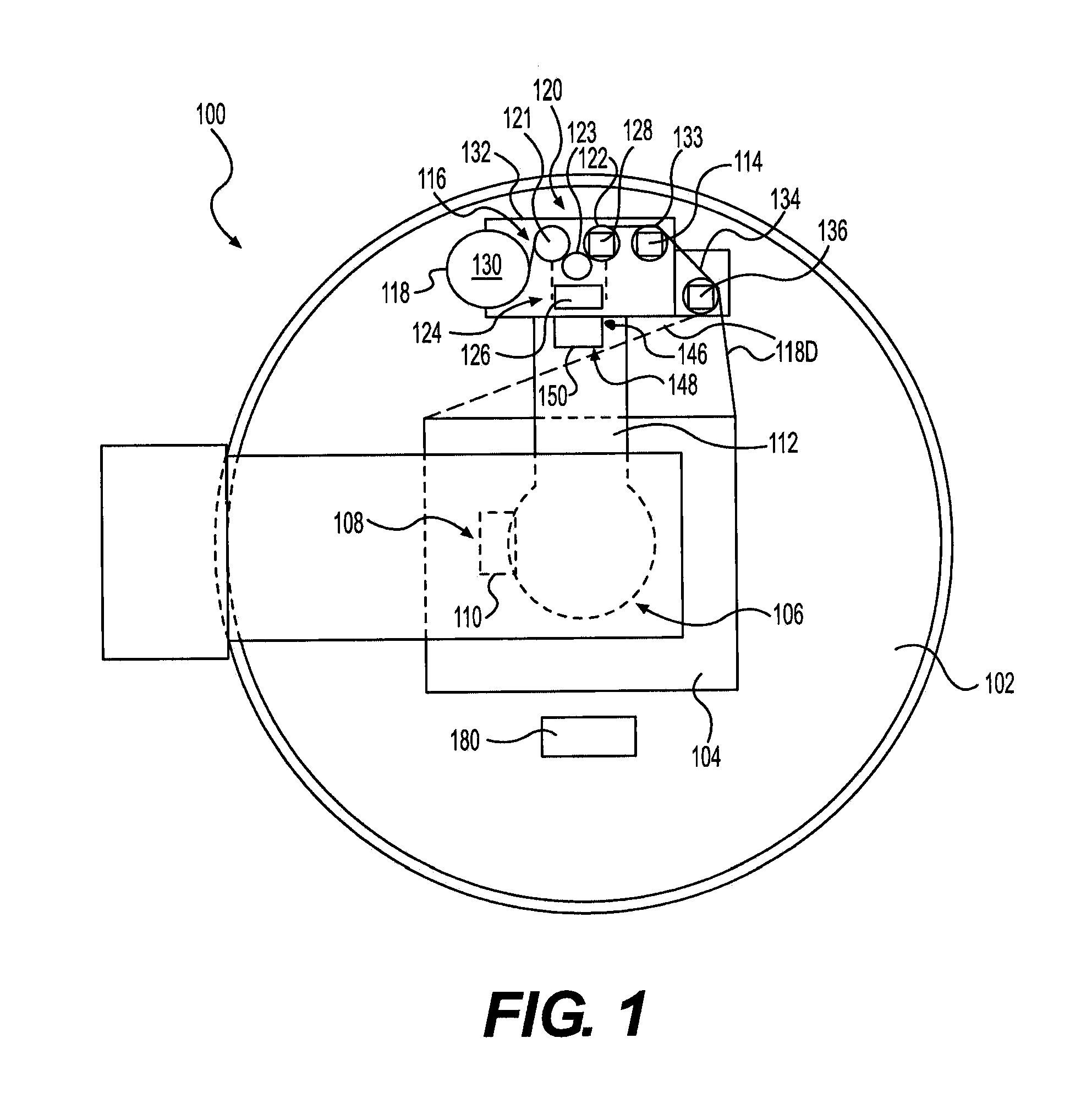
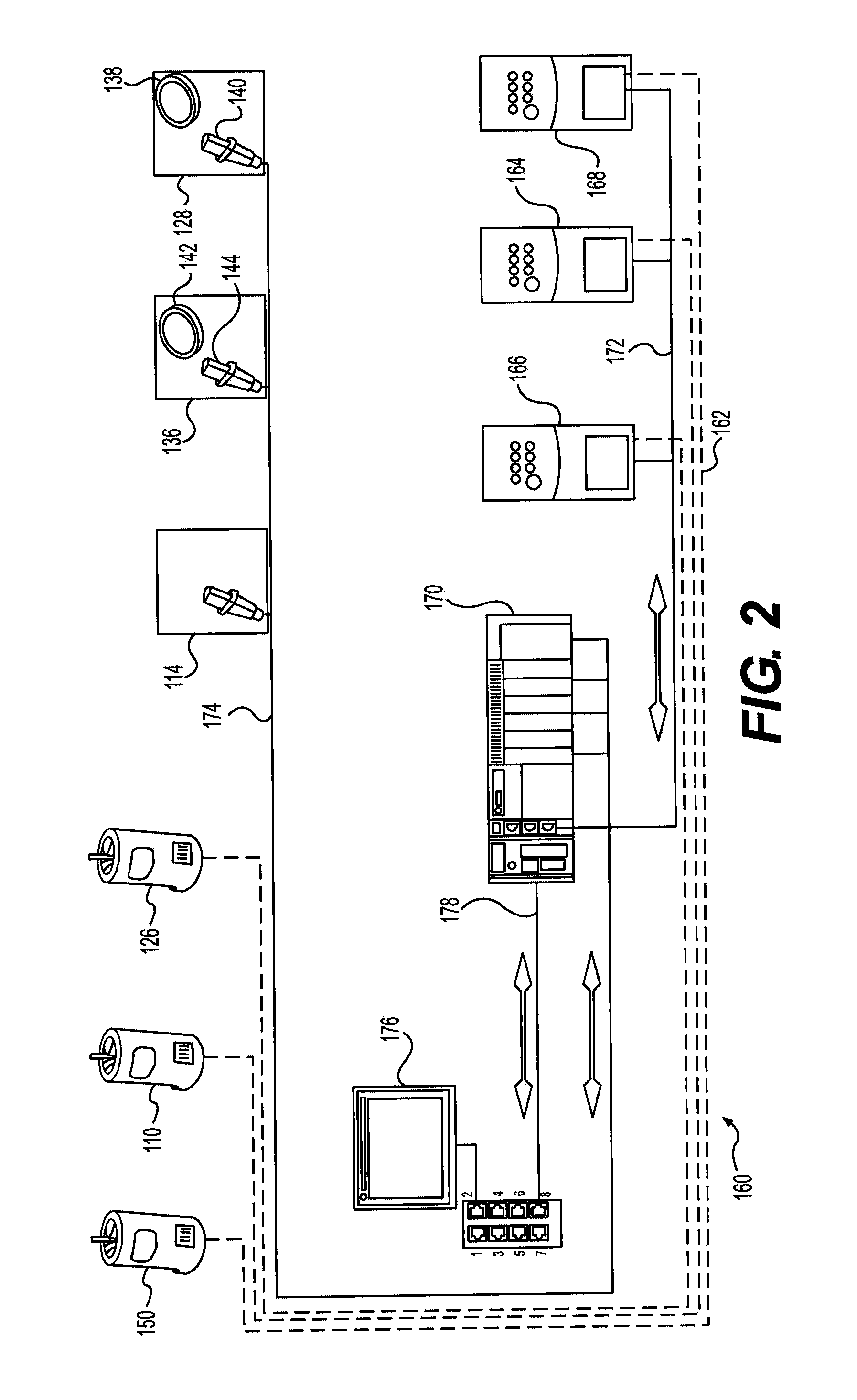
[0025]Reference will now be made in detail to present embodiments of the disclosure, examples of which is illustrated in the accompanying drawings. Wherever possible, the same reference numbers will be used throughout the drawings to refer to the same or like parts. The disclosures of each of U.S. Pat. No. 4,418,510, entitled “STRETCH WRAPPING APPARATUS AND PROCESS,” and filed Apr. 17, 1981; U.S. Pat. No. 4,953,336, entitled “HIGH TENSILE WRAPPING APPARATUS,” and filed Aug. 17, 1989; U.S. Pat. No. 4,503,658, entitled “FEEDBACK CONTROLLED STRETCH WRAPPING APPARATUS AND PROCESS,” and filed Mar. 28, 1983; U.S. Pat. No. 4,676,048, entitled “SUPPLY CONTROL ROTATING STRETCH WRAPPING APPARATUS AND PROCESS,” and filed May 20, 1986; U.S. Pat. No. 4,514,955, entitled “FEEDBACK CONTROLLED STRETCH WRAPPING APPARATUS AND PROCESS,” and filed Apr. 6, 1981; U.S. Pat. No. 6,748,718, entitled “METHOD AND APPARATUS FOR WRAPPING A LOAD,” and filed Oct. 31, 2002; U.S. Patent Application Publication No. ...


PUM

PropertyMeasurementUnit
speedaaaaaaaaaa
rotationaaaaaaaaaa
distanceaaaaaaaaaa

Abstract

A control system for a wrapping apparatus may include a packaging material dispenser configured to dispense packaging material for wrapping a load. The control system may also include at least one sensor assembly configured to generate a signal based on instantaneous demand for packaging material at the load. The control system may further include a controller configured to control operation of the packaging material dispenser based at least in part on the signal.

Description

[0001]This application is a continuation-in-part of application Ser. No. 12 / 349,929, filed Jan. 7, 2009, which claims priority under 35 U.S.C. §119 of Provisional Application No. 61 / 006,338, filed Jan. 7, 2008, the disclosures of which are incorporated herein by reference in their entirety. This application claims priority under 35 U.S.C. §119 of Provisional Application No. 61 / 258,740, filed Nov. 6, 2009, the disclosure of which is incorporated herein by reference in its entirety.TECHNICAL FIELD[0002]The present disclosure relates to an apparatus and a method for wrapping a load with packaging material, and more particularly, to dispensing packaging material for wrapping a load based on demand.BACKGROUND[0003]Various packaging techniques have been used to build a load of unit products and subsequently wrap them for transportation, storage, containment and stabilization, protection and waterproofing. One system uses wrapping machines to stretch, dispense, and wrap packaging material ...

Claims


Application Information

Patent Timeline
Patent Type & Authority Applications(United States)
IPC IPC(8): B65B11/02B65B57/04
CPCB65B11/025B65B11/045B65B2210/20B65B2011/002B65B2210/18B65B57/00B65B57/04B65B65/02
Inventor LANCASTER, III, PATRICK R.MITCHELL, MICHAELHARRIS, THOMASJANES, SR., ROBERT D.JOHNSON, RICHARD L.
Owner LANTECH COM
Why Eureka
Try Eureka