Cooling structure for internal combustion engine

Active Publication Date: 2011-06-09
HONDA MOTOR CO LTD
View PDF8 Cites 15 Cited by
  • Summary
  • Abstract
  • Description
  • Claims
  • Application Information

AI Technical Summary

Benefits of technology

[0027]In the foregoing configuration, the fixing members provided in the respective opposite end portions of the spacer in the cylinder row line direction are put in pressure contact with the inner wall surface of the water jacket. For this reason, the spacer is stretched outward in the cylinder row line direction by reaction forces which the fixing members receive from the inner wall surface of the water jacket, and accordingly deforms in such a wa

Problems solved by technology

This leads to a problem that: the flow of the cooling water is obstructed around the support legs; and the cooling performance is deteriorated.
When the flow of the cooling water is obstru

Method used


Image

  • Cooling structure for internal combustion engine
  • Cooling structure for internal combustion engine
  • Cooling structure for internal combustion engine

Examples


Example

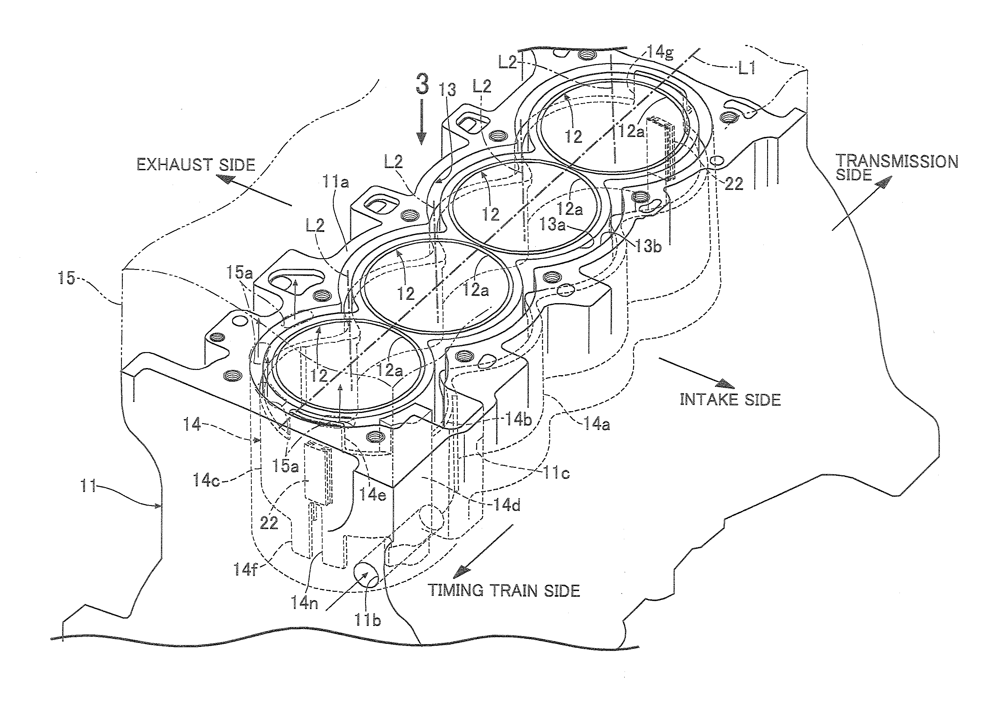
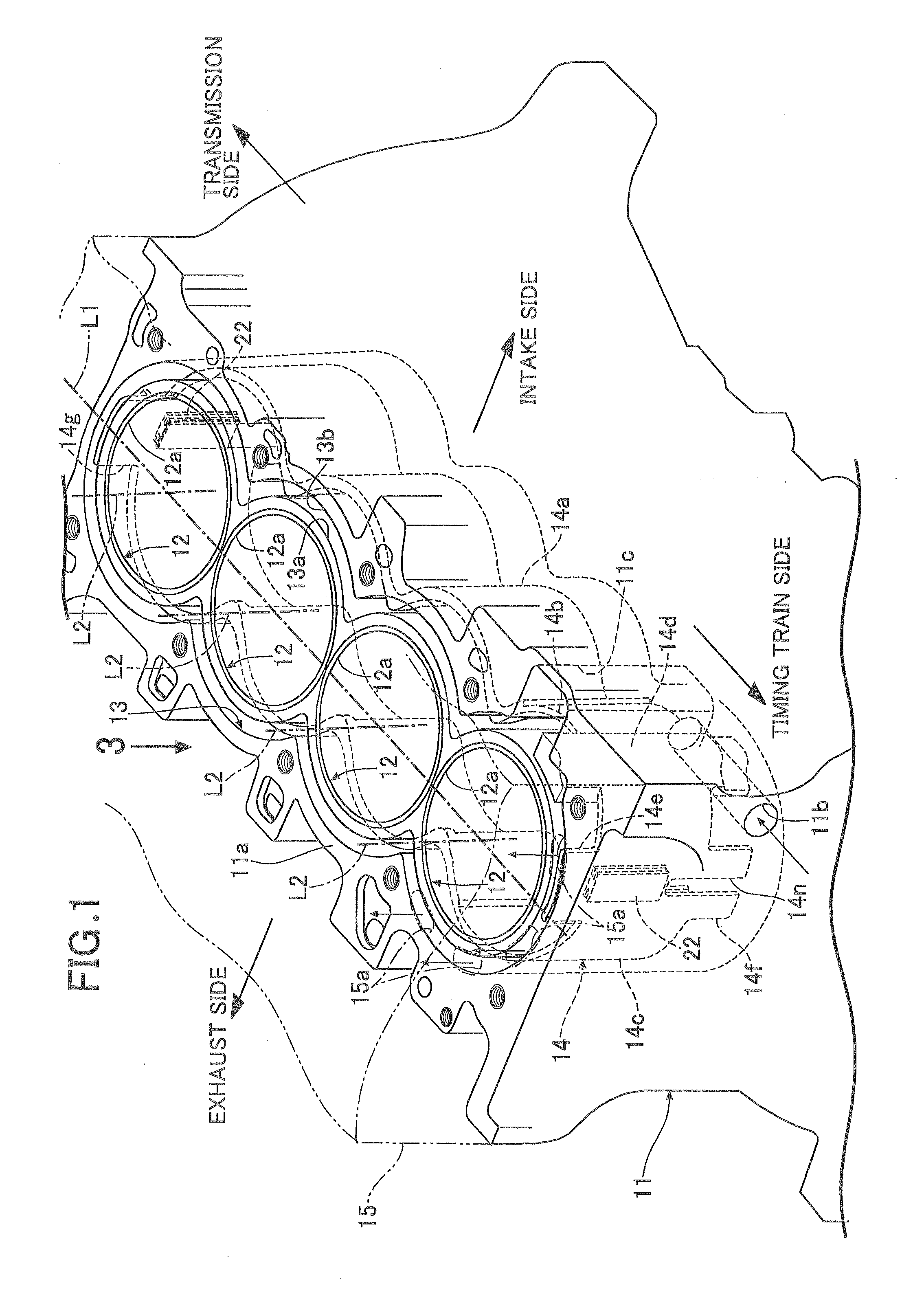
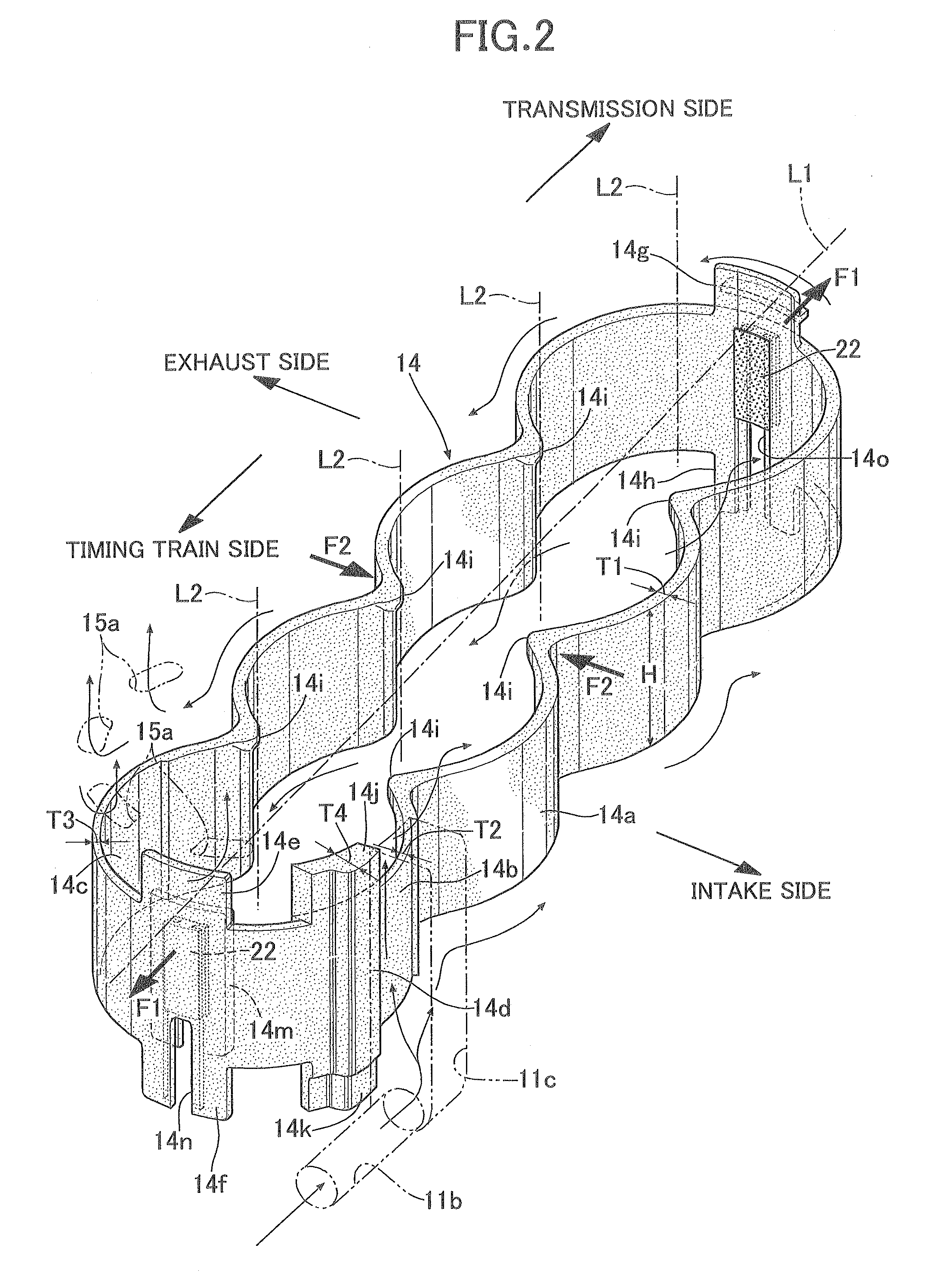
[0069]Descriptions will be hereinbelow provided for a first embodiment of the present invention on the basis of FIGS. 1 to 12C.

[0070]As shown in FIG. 1, four cylinder sleeves 12 are embedded along a cylinder row line L1 in a cylinder block 11 of an internal combustion engine with four cylinders mounted in a straight line. A water jacket 13 is formed to surround the outer peripheral surfaces of the respective cylinder sleeves 12. The cylinder block 11 according to this embodiment is of a Siamese type, and no portion of the water jacket 13 is formed between each neighboring two of the cylinder sleeves 12. Thereby, the shortening of the dimension of the internal combustion engine in the cylinder row line L1 direction is achieved. The water jacket 13 opened in a deck surface 11a of the cylinder block 11 extends downward from the deck surface 11a toward a crankcase up to a certain depth. A spacer 14 made of a synthetic resin is arranged in an interstice between an inner wall surface 13a ...

Example

[0116]Next, descriptions will be provided for a second embodiment of the present invention on the basis of FIGS. 13 to 23B.

[0117]Note that: reference signs used for the second and third embodiments are independent of the reference signs used for the first embodiment; and the same reference signs do not necessarily denote the same members.

[0118]FIG. 13 shows one bank of a cylinder block 11 of a V-type internal combustion engine with six cylinders. Three cylinder sleeves 12 are embedded in the cylinder block 11 along a cylinder row line L1. A water jacket 13 is formed to surround the outer peripheral surfaces of the respective cylinder sleeves 12. The cylinder block 11 according to this embodiment is of a Siamese type, and no portion of the water jacket 13 is formed between the neighboring cylinder sleeves 12. Accordingly, the water jacket 13 surrounds the three cylinder sleeves 12 as a whole, instead of surrounding the outer peripheral surfaces of the respective three cylinder sleeve...

Example

[0152]Next, descriptions will be provided for a third embodiment of the present invention on the basis of FIG. 24.

[0153]In the second embodiment, the upper support legs 14i, 14i are each shaped like a pin having a circular cross section. On the other hand, in the third embodiment, the upper support legs 14i, 14i are each shaped like a plate curving along the flow of the cooling water. This makes it hard for the cooling water flowing in the upper cooling water passage 13c to be obstructed by the upper support legs 14i, 14i. Furthermore, the upper support legs 14i, 14i are offset downstream in the direction of the flow of the cooling water from the respective connection holes 15, 15c in the cylinder head 15 facing the connecting portions 14g, 14g. This makes it possible to smoothly supply the cooing water to the connection holes 15c, 15c as in the second embodiment. Note that, like the upper support legs 14i, 14i, the lower support legs 14j, 14j may be each shaped like the plate.

[0154...


PUM


Abstract

A spacer arranged inside a water jacket which is formed to surround peripheries of cylinder bores in a cylinder block of an internal combustion engine includes support legs extending in an up-and-down direction from a spacer main body part which partitions the water jacket into an upper and lower cooling water passages. The support legs are disposed in opposite end portions in a cylinder row line direction, where the temperatures of the cylinder bores tend to be lower. Accordingly, even if the flow of cooling water is more or less inhibited by the support legs and the cooling effect deteriorates, it is possible to prevent the temperatures of the respective cylinder bores from becoming different by suppressing the influence to a minimum.

Description

BACKGROUND OF THE INVENTION[0001]1. Field of the Invention[0002]The present invention relates to a cooling structure for an internal combustion engine, in which: a spacer is fitted inside a water jacket which is formed to surround peripheries of a plurality of cylinder bores arranged one after another on a cylinder row line of a cylinder block of the internal combustion engine; and a cooling condition of the cylinder bores is controlled by regulating a flow of cooling water in the water jacket by use of the spacer.[0003]2. Description of the Related Art[0004]Japanese Patent No. 4149322 has made publicly known a cooling structure for an internal combustion engine in which: six spacers for inhibiting the flow of cooling water are arranged inside a water jacket which surrounds peripheries of three cylinder bores arranged in a straight line; an upper support leg and a lower support leg respectively project upward and downward from a spacer main body part of each spacer; and the spacers ...

Claims


Application Information

Patent Timeline
IPC IPC(8): F02B75/18
CPCF01P2003/021F02F1/14F02F1/166F01P7/14F01P3/02
Inventor HAMAKAWA, TAKERUNAKAJIMA, ATSUSHIAKIYAMA, YOSHIHIROKAZUI, YOSHIHISAFUJII, TAKESHITAMURA, KUNIYASUIIDA, YOSHIYUKI
Owner HONDA MOTOR CO LTD
Why Eureka
Try Eureka