Device for cooling a vehicle battery

a vehicle battery and cooling device technology, applied in secondary cell manufacture, electrochemical generators, lighting and heating apparatus, etc., can solve the problems of laborious or costly production, and achieve the effect of convenient and economical manufacture, effective and reliable cooling, and low production cos

Inactive Publication Date: 2011-06-09
BEHR GMBH & CO KG
View PDF13 Cites 95 Cited by
  • Summary
  • Abstract
  • Description
  • Claims
  • Application Information

AI Technical Summary

Benefits of technology

[0006]It is an object of the invention is to provide a device for cooling a motor vehicle battery that can be manufactured easily and economically, and that provides effective and reliable cooling. As a result of the fact that the cooling element including the passages is designed as at least one extruded profile, production costs c...

Problems solved by technology

A number of proposals for efficient cooling of such components...

Method used


Image

  • Device for cooling a vehicle battery
  • Device for cooling a vehicle battery
  • Device for cooling a vehicle battery

Examples


Embodiment Construction

[0059]In each case, the electric elements cooled in the exemplary embodiments described below are lithium-ion batteries, while other elements, such as NiMH batteries or supercaps, may also be provided depending on requirements.

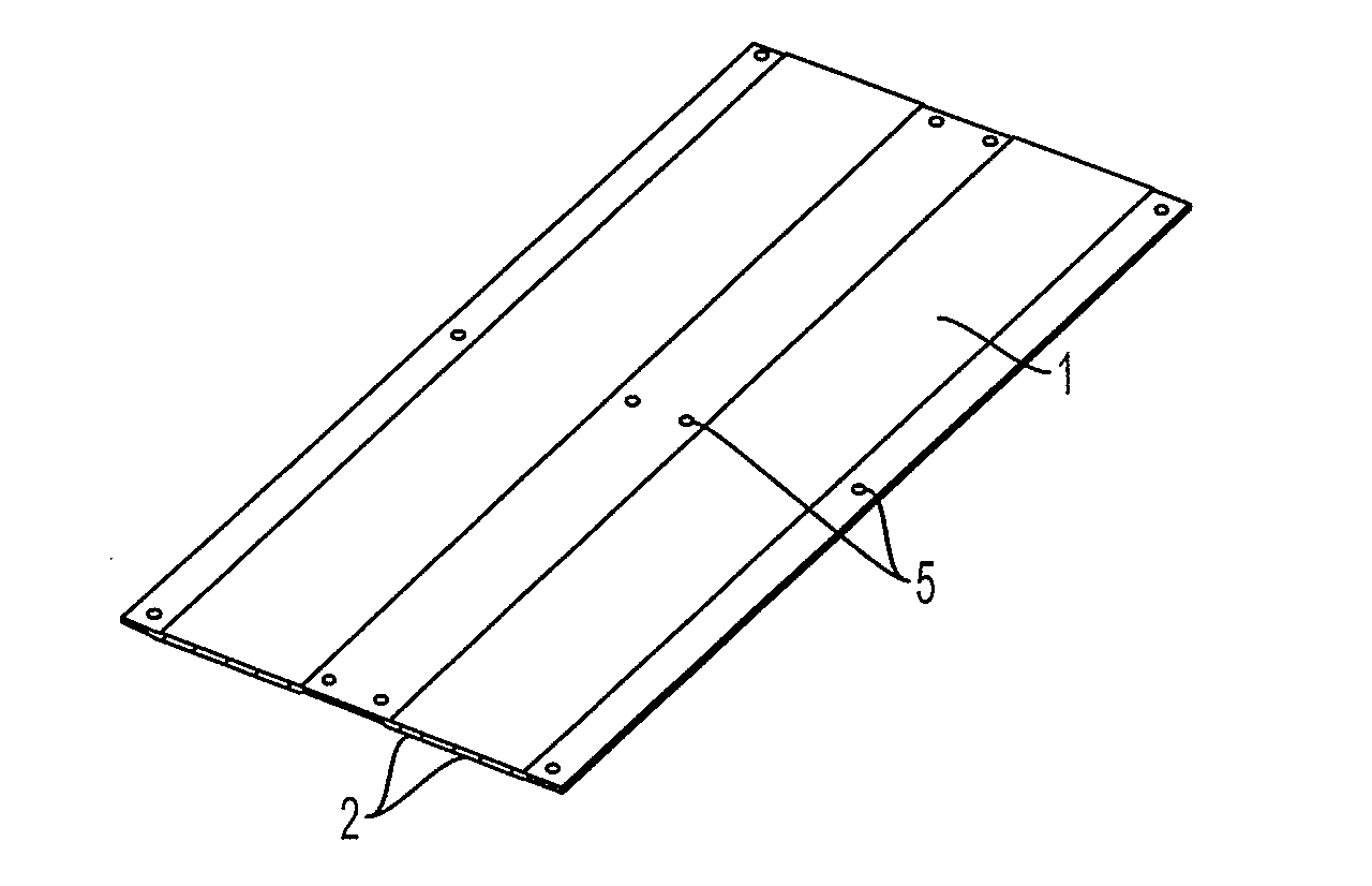
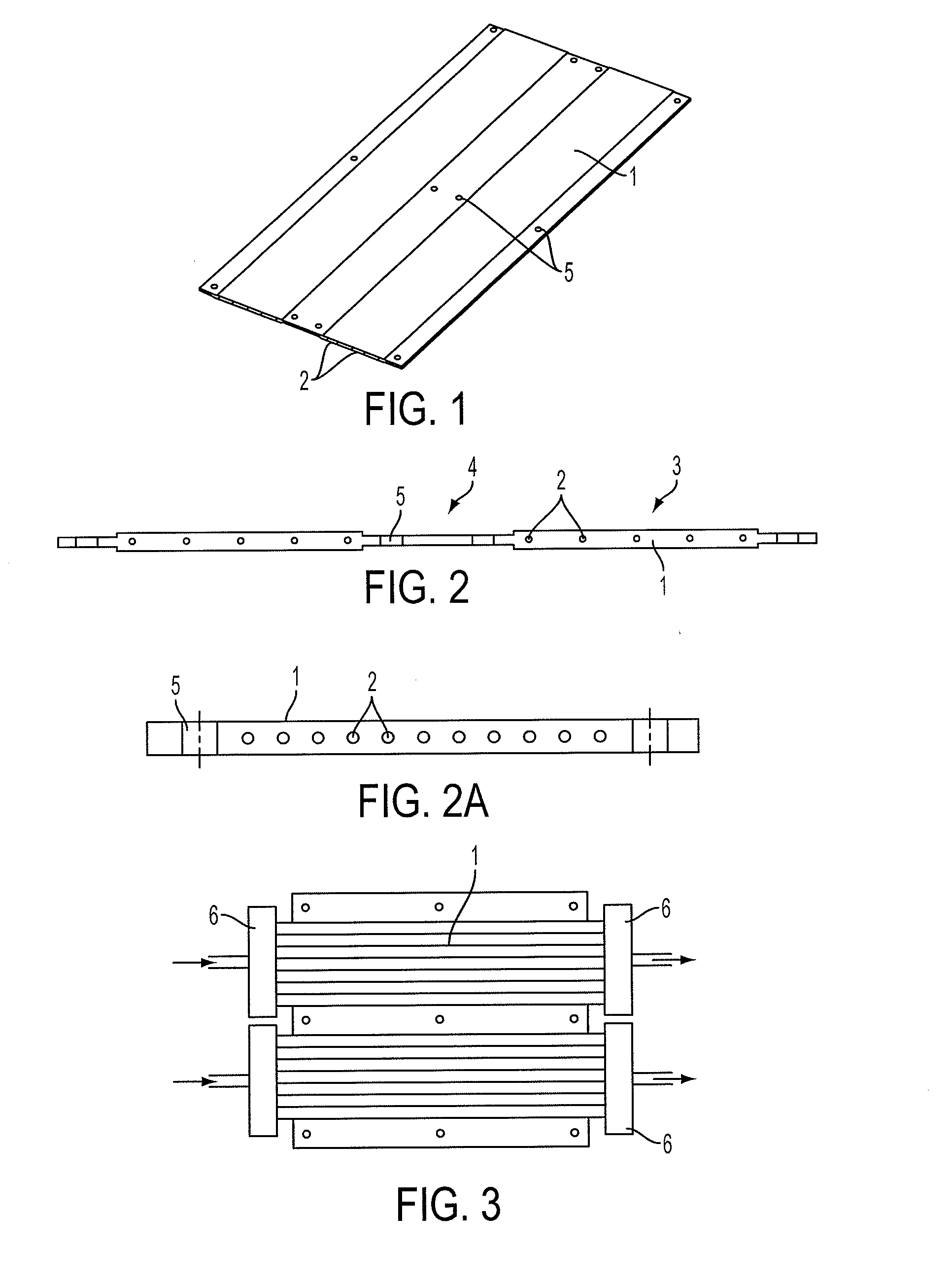
[0060]In the first exemplary embodiment shown in FIG. 1 and FIG. 2, the cooling element is designed as an extruded aluminum profile 1 with a plurality of passages 2 arranged next to one another in a transverse direction, which may have a round, polygonal, or other cross-section. Each group of passages 2 constitutes a first region of greater thickness 3 on the cooling element, wherein second regions 4 of smaller thickness are provided between these regions 3 in order to save weight. The second regions are provided with holes 5, by means of which the electrical elements—which are not shown—are affixed to the cooling element, if applicable by additional retaining members.

[0061]In the variation from FIG. 2a, the extruded profile 1 has a constant thickness, althoug...


PUM


Abstract

A device for cooling a vehicle battery is provided that includes a plurality of electrical storage elements, and a cooling element having ducts for a fluid to flow through, wherein the electrical storage elements are in thermal contact with the cooling elements and heat can be transmitted from the storage elements to the fluid, and wherein the cooling element which comprises the ducts is embodied as at least one extruded profile.

Description

[0001]This nonprovisional application is a continuation of International Application No. PCT / EP2009 / 003916, which was filed on Jun. 2, 2009, and which claims priority to German Patent Application No. DE 10 2008 027 293.0, which was filed in Germany on Jun. 6, 2008, and which are both herein incorporated by reference.BACKGROUND OF THE INVENTION[0002]1. Field of the Invention[0003]The invention concerns a device for cooling a vehicle battery.[0004]2. Description of the Background Art[0005]The cooling of electrical energy storage devices of modern motor vehicles poses special demands on account of the sometimes high power density. Such energy storage devices can be used as batteries for electric or hybrid vehicles, among other uses. These can be lithium-ion batteries, supercaps, fuel cells, conventional rechargeable batteries, or combinations of such elements. A number of proposals for efficient cooling of such components are known, although these are often laborious or costly to produ...

Claims


Application Information

Patent Timeline
IPC IPC(8): F28D15/00
CPCF28F3/12H01M8/04007H01M8/24H01M10/0413H01M10/5004F28F2255/16H01M10/5016H01M10/5059H01M10/5071H01M10/5075H01M10/5079H01M10/5008H01M10/625H01M10/6569H01M10/6557H01M10/6567H01M10/617H01M10/6565H01M10/613H01M10/6566F28D7/0066F28F2270/02F28D1/0478Y02E60/50Y02E60/10F28F9/026H01M8/0267H01M8/2483
Inventor HERRMANN, HANS-GEORGMOLDOVAN, FLORIANSCHMID, CAROLINESCHIEHLEN, THOMASISERMEYER, TOBIASSTEINBACH, MARTINECKSTEIN, JUERGENFEHREN-BACHER, CHRISTOPHWIEBELT, ACHIMKOHLBERGER, MARKUSPFENDER, CONRADHECKENBERGER, THOMAS
Owner BEHR GMBH & CO KG
Why Eureka
Try Eureka