

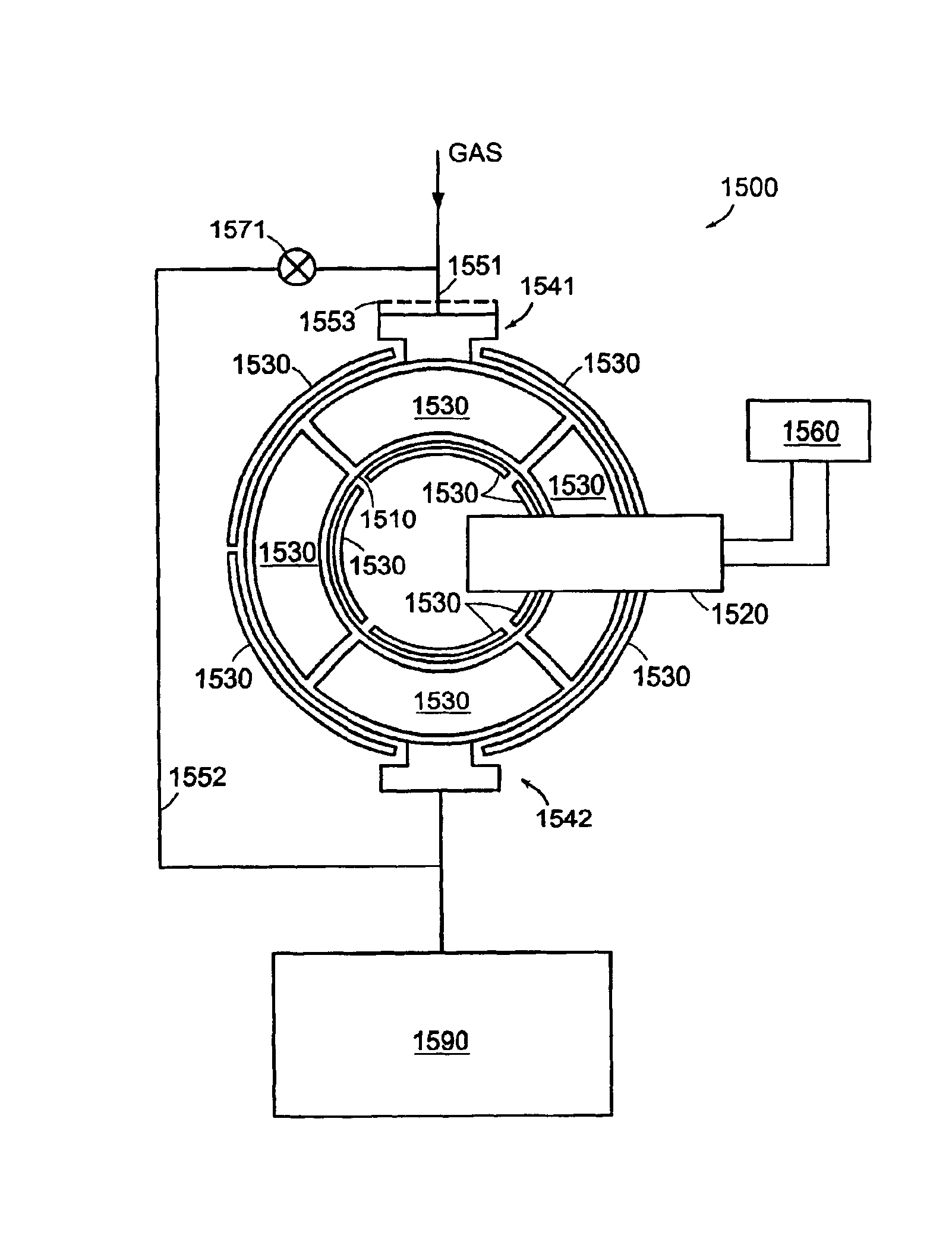
Toroidal low-field reactive gas and plasma source having a dielectric vacuum vessel
a dielectric vacuum vessel and reactive gas technology, applied in plasma welding apparatus, plasma discharge tubes, manufacturing tools, etc., can solve the problems of microwave power being generally more expensive to produce, microwave-based remote plasma sources are generally more expensive than rf sources, and the practical use of those sources is limited. , to achieve the effect of reliable ignition of plasma in a vessel, effective and reliable cooling of the vessel, and a larger area and/or longer ignition electrodes
- Summary
- Abstract
- Description
- Claims
- Application Information
AI Technical Summary
Benefits of technology
Problems solved by technology
Method used
Image

Examples
Embodiment Construction
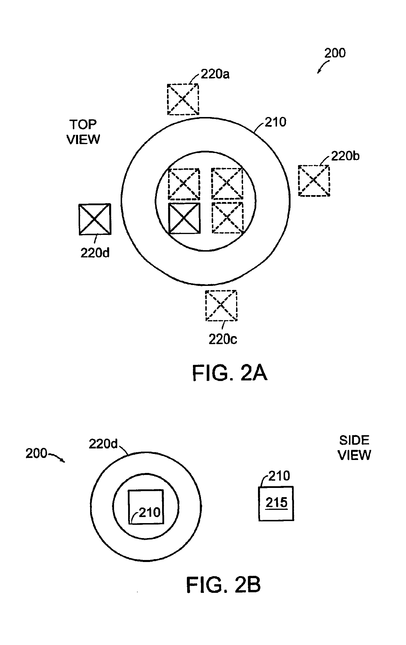
Definitions—A “plasma system” is an apparatus that includes plasma generation components, and can include materials processing components. A plasma system can include one or more vessels, power supply components, metrology components, control components, and other components. Processing can occur in one or more vessels and / or in one or more processing chambers in communication with the one or more vessels. A plasma system can be a source of plasma or reactive gas species generated in a plasma or can be a complete processing tool.
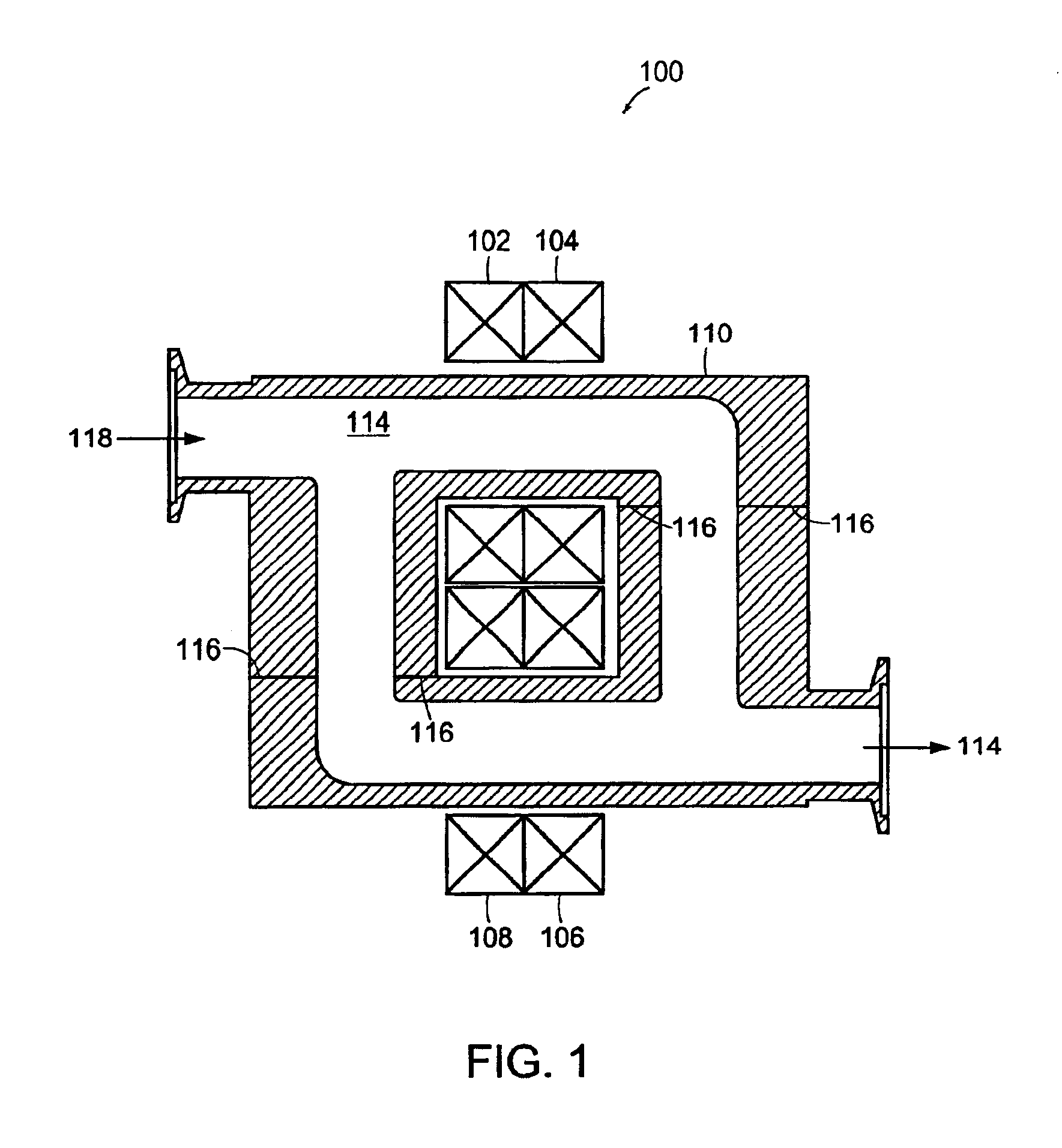
A “vessel” is a container or portion of a container that contains a gas and / or a plasma, and within which a plasma can be ignited and or / maintained. A toroidal vessel includes at least one dielectric portion, or is formed entirely of dielectric material. A vessel can also be referred to as a plasma body. A vessel is combined with other components, such as power generation and cooling components to form a plasma processing system. A vessel can define channels...
PUM
| Property | Measurement | Unit |
|---|---|---|
| pressure | aaaaa | aaaaa |
| temperature | aaaaa | aaaaa |
| power | aaaaa | aaaaa |
Abstract
Description
Claims
Application Information