Visual Indication Of Settings Changes On A Ventilator Graphical User Interface

Active Publication Date: 2011-06-09
TYCO HEALTHCARE GRP LP
View PDF105 Cites 144 Cited by
  • Summary
  • Abstract
  • Description
  • Claims
  • Application Information

AI Technical Summary

Problems solved by technology

Due to the complexity of ventilators, it may be difficult for a clinician to identify where changes to ventilator settings may be entered or edited.
Further, it may be difficult for a clinician to ident

Method used


Image

  • Visual Indication Of Settings Changes On A Ventilator Graphical User Interface
  • Visual Indication Of Settings Changes On A Ventilator Graphical User Interface
  • Visual Indication Of Settings Changes On A Ventilator Graphical User Interface

Examples


Embodiment Construction

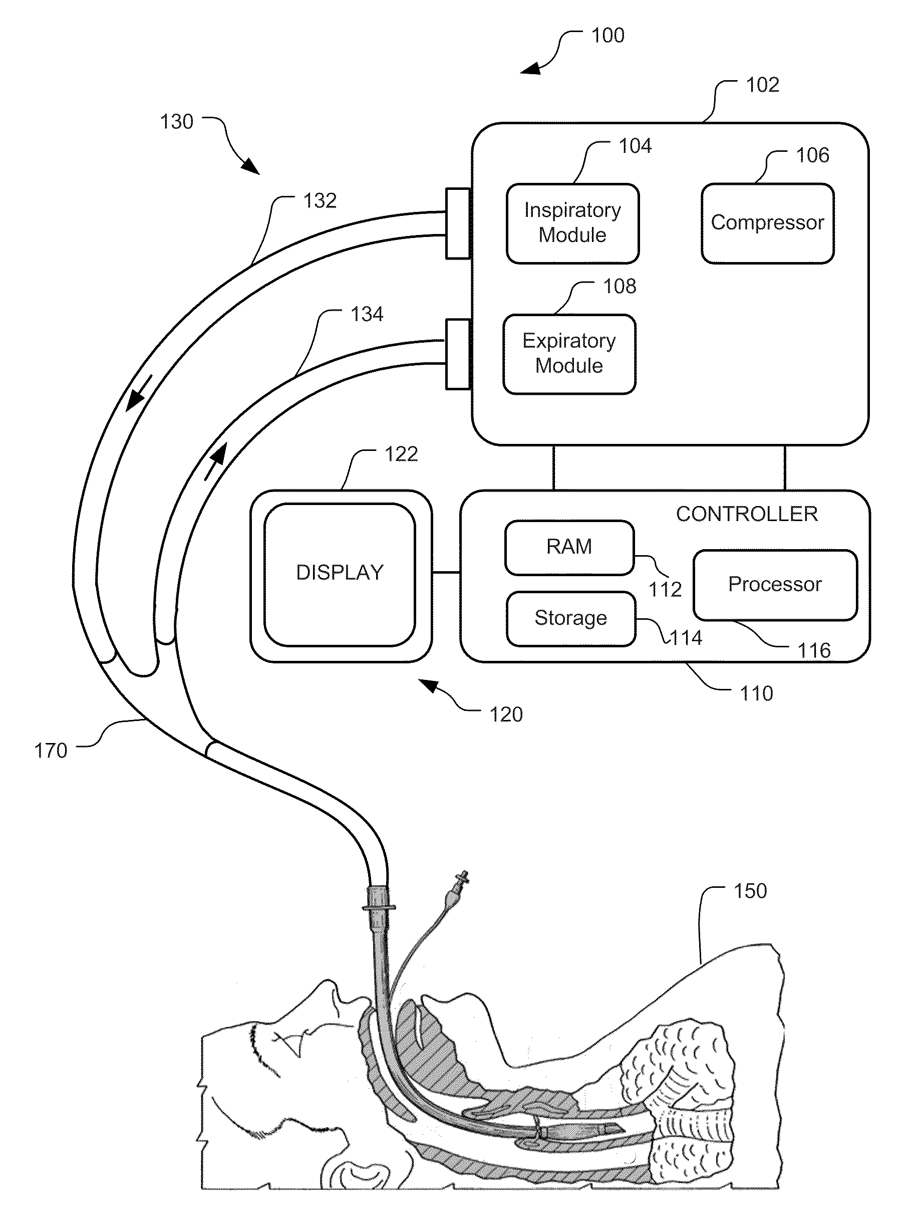
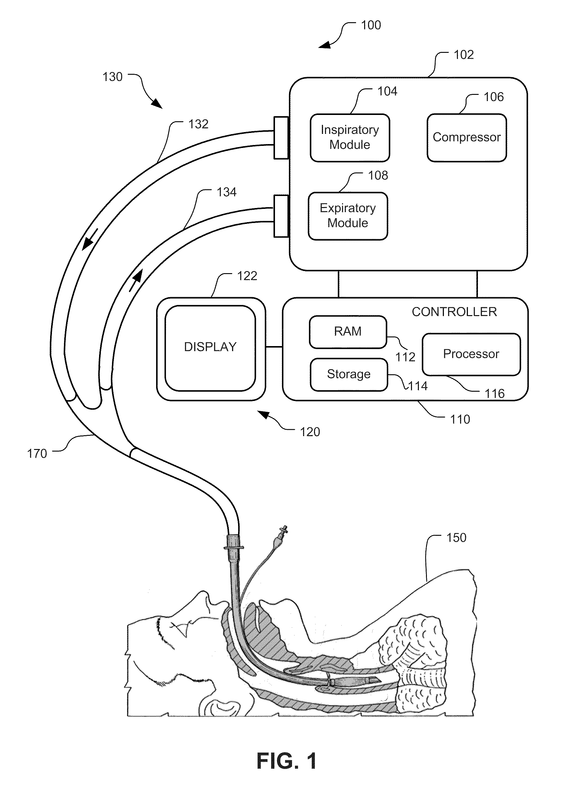
[0020]Although the techniques introduced above and discussed in detail below may be implemented for a variety of medical devices, the present disclosure will discuss the implementation of these techniques for use in a mechanical ventilator system. The reader will understand that the technology described in the context of a ventilator system could be adapted for use with other therapeutic equipment having graphical user interfaces for configuring and changing settings.

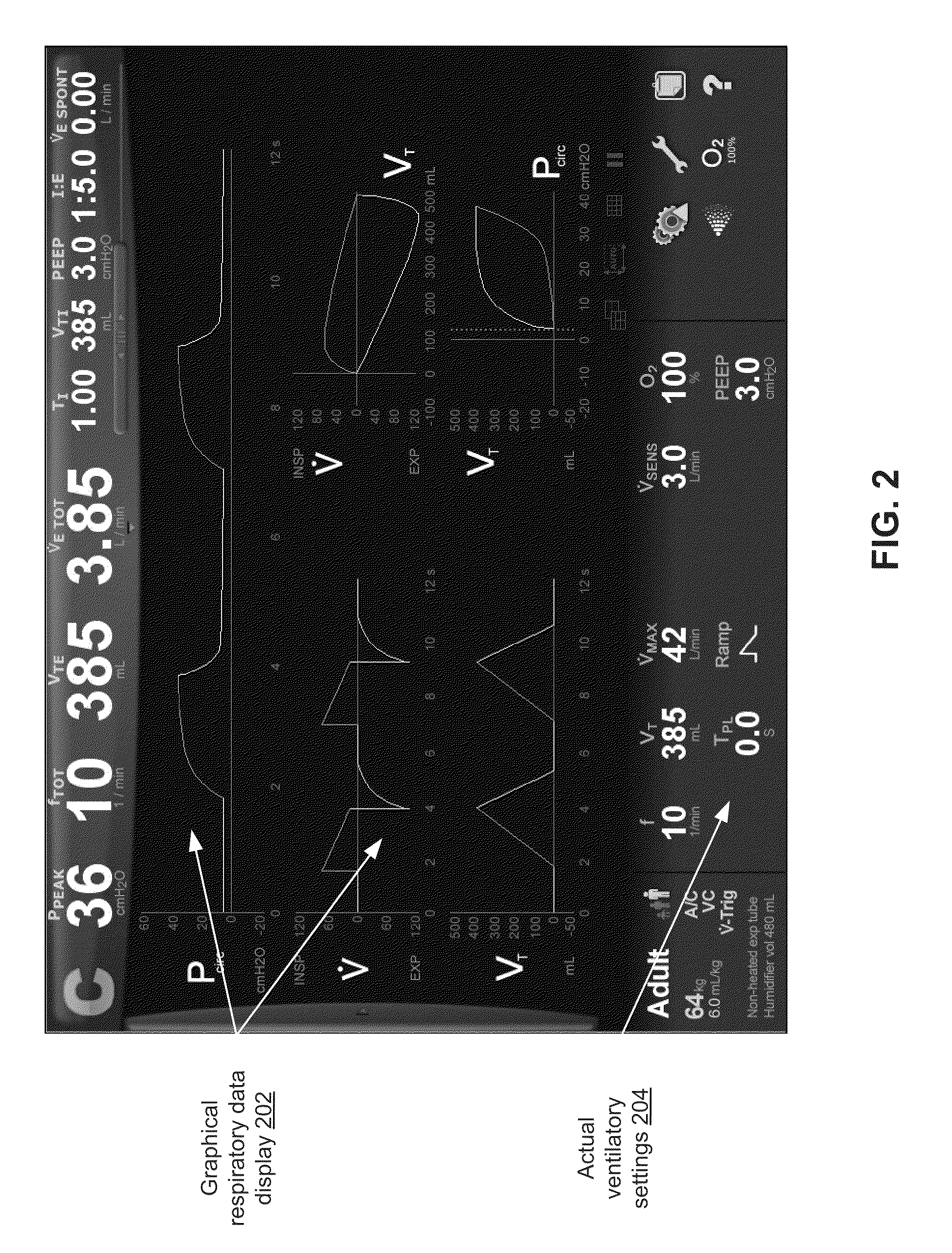
[0021]This disclosure describes systems and methods for accessing and changing ventilatory settings. Specifically, embodiments may provide an animation window that is easily accessed from any number of displayed ventilatory settings. In fact, the animation window may expand from the displayed ventilatory settings and may provide a number of setting access elements, each corresponding to an individual ventilatory setting, for efficiently adjusting displayed ventilatory settings. Settings may be changed and accepted via t...


PUM


Abstract

This disclosure describes improved systems and methods for visualizing the application of changes to respiratory settings in a ventilatory system. Specifically, the present disclosure provides for a setup animation window that may be easily accessed from a setup icon, for example, and also provides for a settings animation window that may be easily accessed from any number of displayed ventilatory settings. In fact, the setup animation window may be directly accessed by touching, clicking, or otherwise selecting the setup icon and may expand from the setup icon to display any number of settings access elements. Alternatively, the settings animation window may be directly accessed by touching, clicking, or otherwise selecting any one of the displayed ventilatory settings and may expand from the displayed ventilatory settings to provide corresponding settings access elements. The corresponding settings access elements each corresponding to an individual ventilatory setting of the displayed ventilatory settings and useful for efficiently adjusting the displayed ventilatory settings. Ventilatory settings may be changed and accepted via either animation window. In one embodiment, upon accepting settings changes from the settings animation window, settings may appear to visually float or fade into the displayed ventilatory settings. In this embodiment, clinicians may view the settings changes as they are accepted and applied to the GUI.

Description

RELATED APPLICATIONS[0001]This application is related to co-owned U.S. patent application Ser. No. ______, entitled “Display of Respiratory Data on a Ventilator Graphical User Interface”; U.S. patent application Ser. No. ______, entitled “Display and Access to Settings on a Respiratory Ventilator Graphical User Interface”; U.S. patent application Ser. No. ______, entitled “Visual Indication of Alarms on a Ventilator Graphical User Interface”; and U.S. patent application Ser. No. ______, entitled “Quick Initiation of Respiratory Support via a Ventilator User Interface”; all filed on ______, the entire disclosures of all of which are hereby incorporated herein by reference.INTRODUCTION[0002]A ventilator is a device that mechanically helps patients breathe by replacing some or all of the muscular effort required to inflate and deflate the lungs. During ventilation, the ventilator may be configured to display useful information to the clinician and to receive inputs and commands from th...

Claims


Application Information

Patent Timeline
IPC IPC(8): G06F3/048
CPCG06F19/3406G06F3/0488A61M2205/505G16H40/63
Inventor SKIDMORE, JOHN P.PORTER, OLEN D.PALMER, MARC E.
Owner TYCO HEALTHCARE GRP LP
Why Eureka
Try Eureka