RFID reader and signal receiving method thereof

Inactive Publication Date: 2011-06-16
ELECTRONICS & TELECOMM RES INST
View PDF7 Cites 8 Cited by
  • Summary
  • Abstract
  • Description
  • Claims
  • Application Information

AI Technical Summary

Benefits of technology

[0017]The present invention is to solve the above problems. It is an object of the present invention to provide an RFID reader capable of suppressing transmission leakage current and a signal receiving method thereof.
[0023]According to the exemplary embodiments of the present invention, the RFID reader includes the band stop filter with good frequency selection characteristic quality added to the existing RFID reader receiver to suppress the transmission leakage signals and extract only the modulation components including the tag information among the backscattered signals from the tag, thereby making it possible to improve the recognition distance and recognition rate of the reader.
[0024]In particular, the quartz oscillator used in the band stop filter is used in the down conversion and up conversion of the frequency band, such that frequency synchronization is facilitated and a separate frequency generator for up / down conversion of frequency is not needed.
[0025]In addition, in the general RFID system, the phase of the reader transmission leakage signal changes every moment according to the radio environment, such that it is difficult for the RFID system to control the phase at all times; however, in the present invention, the band stop filter suppresses the transmission leakage signals in the same circuit, such that the RFID system is not affected by the change in the phase, thereby making it possible to optimally suppress the transmission leakage signals.

Problems solved by technology

Therefore, the isolation between the transmitter and receiver is deteriorated by the signal coupling within the space.
In addition, the change in the antenna pattern occurs according to the ambient environment of the antenna and the change in the antenna pattern leads to the coupling of the transmission and reception signals, such that it is difficult to maintain the desired isolation.
In particular, it is a disadvantage in that the size of the RFID system becomes large due to the use of two antennas.
However, the isolation between the transmitter and receiver is not generally large in the circulator or the directional coupler, such that a part of the transmission signals is leaked and introduced in the direction of the reader receiver.
As a result, the reader receiver simultaneously receives the transmission leakage signals leaked from the reader transmitter and the backscattered signals from the tag.
Therefore, there is a problem in that the reader receiver is difficult to recover only the modulation signal components including the tag information among the backscattered signals from the tag.

Method used


Image

  • RFID reader and signal receiving method thereof
  • RFID reader and signal receiving method thereof
  • RFID reader and signal receiving method thereof

Examples


Embodiment Construction

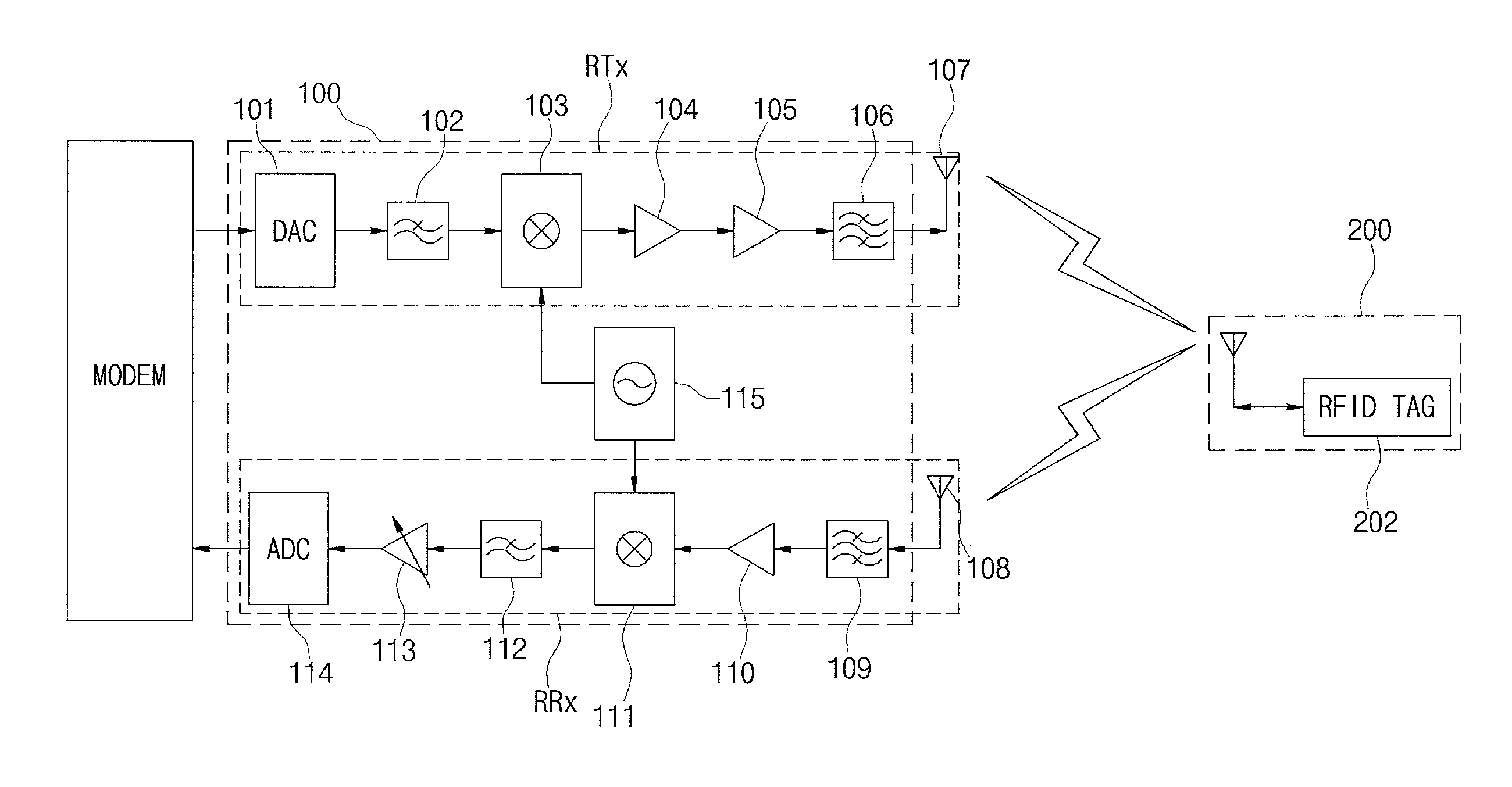
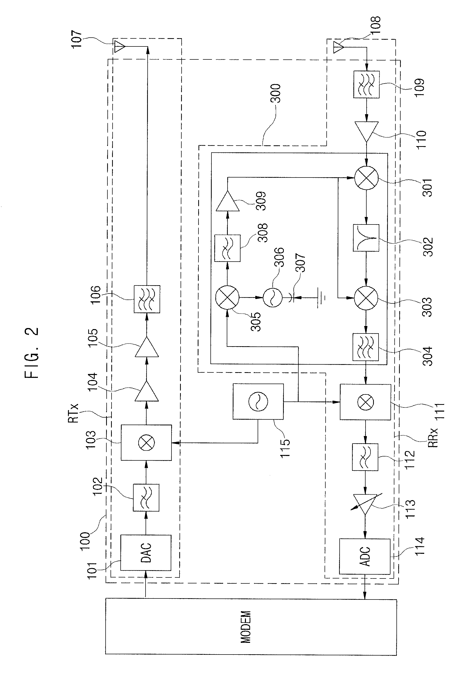
[0032]Advantages and features of the present invention and methods to achieve them will be elucidated from exemplary embodiments described below in detail with reference to the accompanying drawings. However, the present invention is not limited to exemplary embodiment disclosed herein but will be implemented in various forms. The exemplary embodiments is provided by way of example only so that a person of ordinary skilled in the art to fully understand the disclosures of the present invention and the scope of the present invention. Therefore, the present invention will be defined only by the scope of the appended claims. Meanwhile, terms used in the present invention are to explain exemplary embodiments rather than limiting the present invention. Also, when an element is referred to as being “connected to” another element, it can be directly connected to another element or be indirectly connected to another element with one or more intervening elements interposed therebetween. In t...


PUM


Abstract

The present invention relates to an RFID reader and a signal receiving method thereof. The RFID reader according to one embodiment of the present invention down-converts transmission leakage signals introduced into a reader receiver and then suppresses them through a band stop filter in a low frequency band and up-converts them, thereby making it possible to effectively suppress the transmission leakage signals.

Description

CROSS-REFERENCE TO RELATED APPLICATIONS[0001]This application claims priority under 35 U.S.C. §119 to Korean Patent Application No. 10-2009-0124978, filed on Dec. 15, 2009, in the Korean Intellectual Property Office, the disclosure of which is incorporated herein by reference in its entirety.BACKGROUND OF THE INVENTION[0002]1. Field of the Invention[0003]The present invention relates to a radio frequency identification (RFID) reader capable of suppressing transmission leakage signals, including a band stop filter and a signal receiving method thereof.[0004]2. Description of the Related Art[0005]Generally, an RFID technology provides services such as positioning, remote processing, and managing of objects, information exchange between objects, etc., by attaching tags to each object, wirelessly recognizing unique identifiers (IDs) of objects, and collecting, storing, processing, and tracking the corresponding information on the objects. The RFID technology is forecasted to form a new ...

Claims


Application Information

Patent Timeline
IPC IPC(8): H04Q5/22
CPCG06K7/10217H04B5/00G06K17/00
Inventor JUNG, JAE YOUNGSHIN, DONG BEOMLEE, SANG YEOUNCHOI, GIL YOUNGLEE, HEYUNG SUBCHAE, JONG SUK
Owner ELECTRONICS & TELECOMM RES INST
Why Eureka
Try Eureka