Radio-tracking method, system and devices

Inactive Publication Date: 2011-06-16
TINYTRONIC
View PDF15 Cites 26 Cited by
  • Summary
  • Abstract
  • Description
  • Claims
  • Application Information

AI Technical Summary

Benefits of technology

[0009]Conventional radiotracking units have the drawback of their large size. However, they have the advantage of a greater sensitivity when receiving signals, and therefore can receive very weak signals with very low intensity. Similarly, they can receive with considerable accuracy signals emitted from very large distances, in the

Problems solved by technology

Conventional radiotracking units have the drawback of their large size.
However, their sensitivity to signal reception is typically lower than that of the conventional devices.
They also do not allow adding information of any type to the pulse emitted by the transmitter.
In addition, if the pulse signal is received with very low intensity due to a temporary high attenuation and the user hears a low amplitude, he or she may obtain an incorrect impression of the distance, believing that the carrier is at a large distance.
Therefore, the radiotracking techniques of the state of the art have the drawback that they only allow estimating the direction of the carrier and cannot determine the actual direction accurately.
They also do not allow determining the distance to the carrier, as they lack the data necessary to determine this distance accurately.
A further drawback of the existing devices is that their angular resolution for determining direction is highly dependent on the directivity of the antenna used.
This process may be inconvenient to the user and therefore hinders their commercialisation.
These devices are not designed to allow a user to locate a carrier that is far from the GPS device of the tracking user.
The great drawback of these de

Method used


Image

  • Radio-tracking method, system and devices
  • Radio-tracking method, system and devices
  • Radio-tracking method, system and devices

Examples


Example

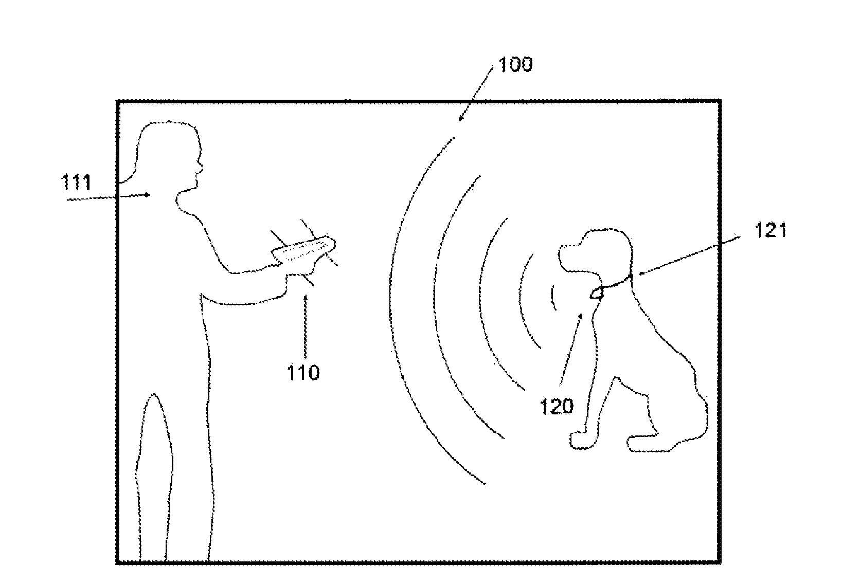
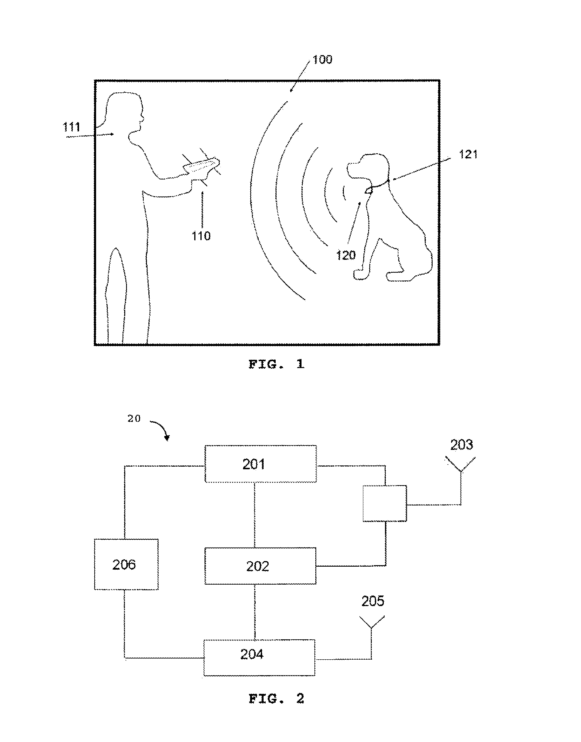
[0040]FIG. 1 shows a system 100 example embodiment of the invention. The system 100 comprises a console device 100 for the user 111, machine, object or animal, wishing to search and track a carrier 121 and a carrier device 120, coupled to the carrier, whether this is an object, person, machine, or animal. The device 120 must be registered with the console 110 to initialise the search and tracking operation.

[0041]The registration operation comprises among others assigning a common working radiofrequency for the two devices, saved in the console under an identification number for the carrier device 120. This number can consist of a name selected by the user to recognise the carrier, or the serial number of the carrier device, or the frequency at which the energy pulses are emitted, or the frequency at which the telemetric data signals are emitted, or a combination thereof. The registration can be implemented by default in factory, or when initialising a carrier with a console, changin...


PUM


Abstract

A device configured to be worn by a target to be located, a console device for displaying information relating to the position, direction and distance of the target with respect to a person using the console, and a system and a method for searching for and locating a target by means of radiotracking.

Description

FIELD OF THE INVENTION[0001]The present invention relates to the field of telecommunications, and in particular to a radiotracking device, for searching for and tracking objects and / or animals and persons.BACKGROUND OF THE INVENTION[0002]The technique of radiotracking allows incorporating emitters to animals, objects or persons, in order to locate them subsequently with a receiver that communicates with the emitter by electromagnetic signals, even at very large distances in the range of several tens of kilometers.[0003]This technique can be used for any application that requires locating an object and subsequently tracking and following the object while it moves. This tracking process is also known as radiotracking. In this document, the terms radiotracking and radiolocation will be used interchangeably, as the device object of the invention provides both the wireless location and tracking functionality by means of radiofrequency.[0004]In the following, the term “carrier” will be us...

Claims


Application Information

Patent Timeline
IPC IPC(8): G01S5/02
CPCA01K11/008A01K15/021G01S13/825G01S5/0072A01K29/005
Inventor LOPEZ POU, ANDRESVAZQUEZ GALLEGO, FRANCISCOCANO CAMPS, ALBERT
Owner TINYTRONIC
Why Eureka
Try Eureka