Camera Angle Compensation in Iris Identification

a technology of iris identification and camera angle compensation, which is applied in the field of capturing and processing images for biometric iris identification, can solve the problems of significant false rejection rate, failure to find a match, false rejection,

Inactive Publication Date: 2011-06-16
EYE CONTROLS
View PDF10 Cites 24 Cited by
  • Summary
  • Abstract
  • Description
  • Claims
  • Application Information

AI Technical Summary

Benefits of technology

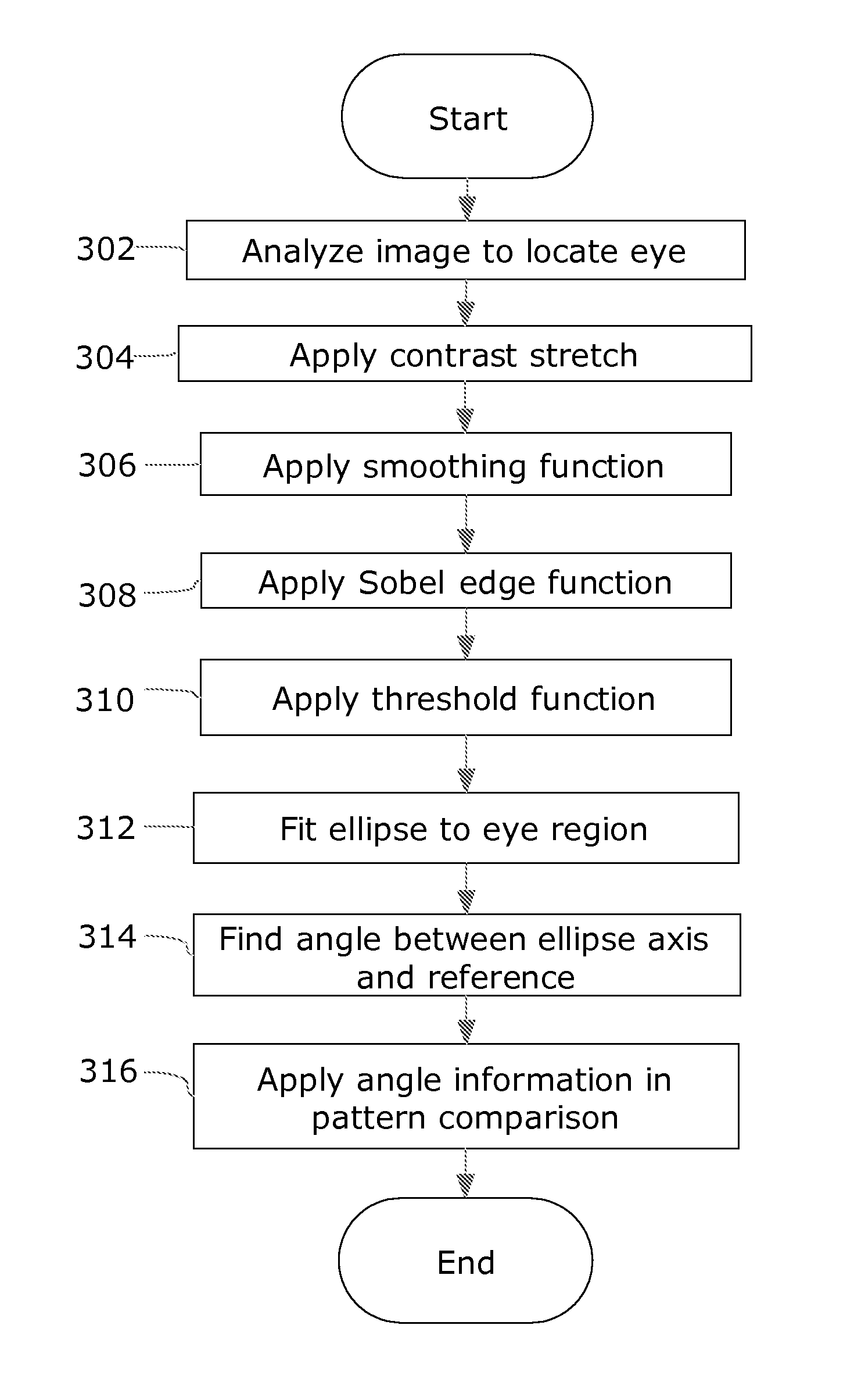
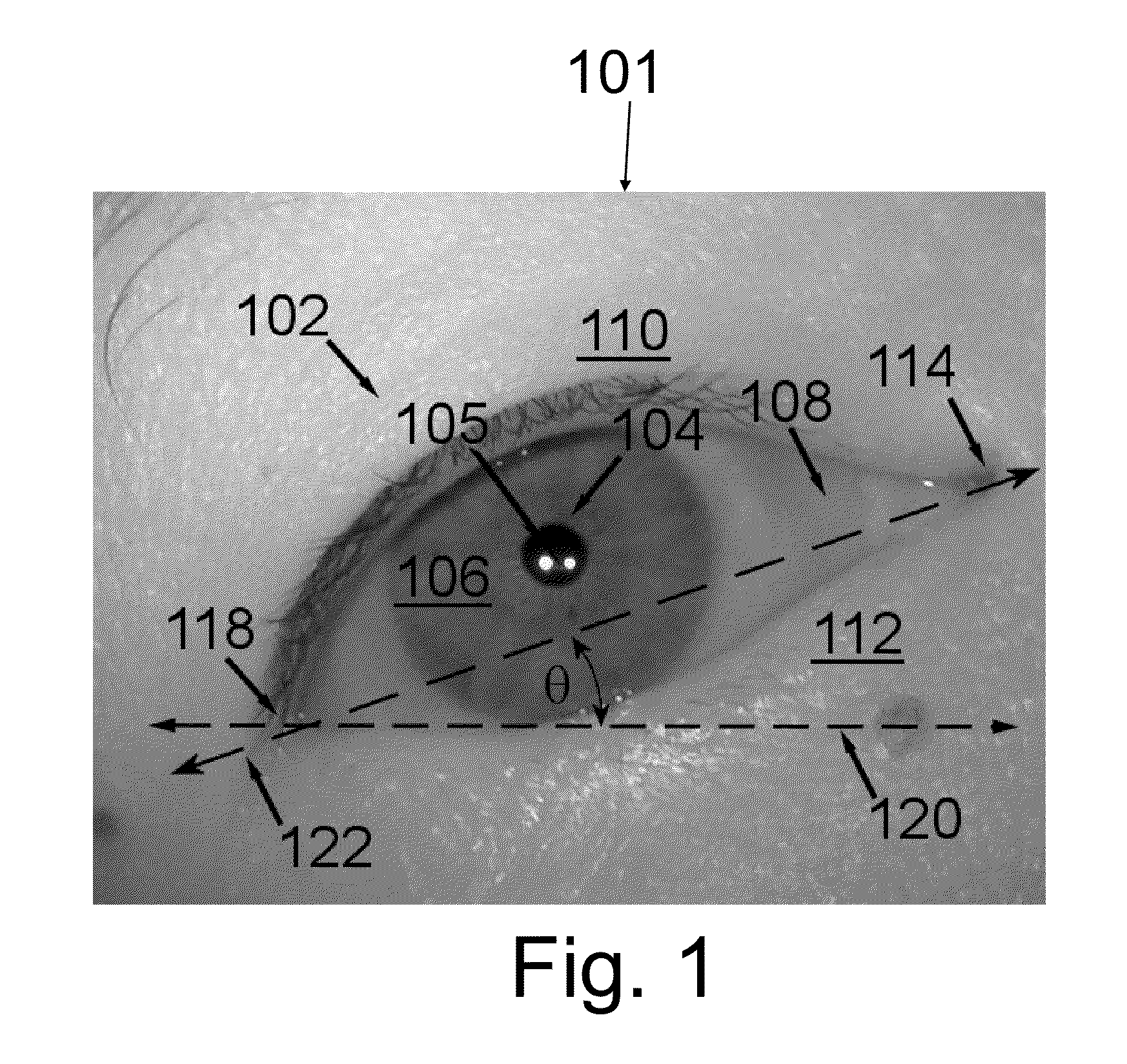
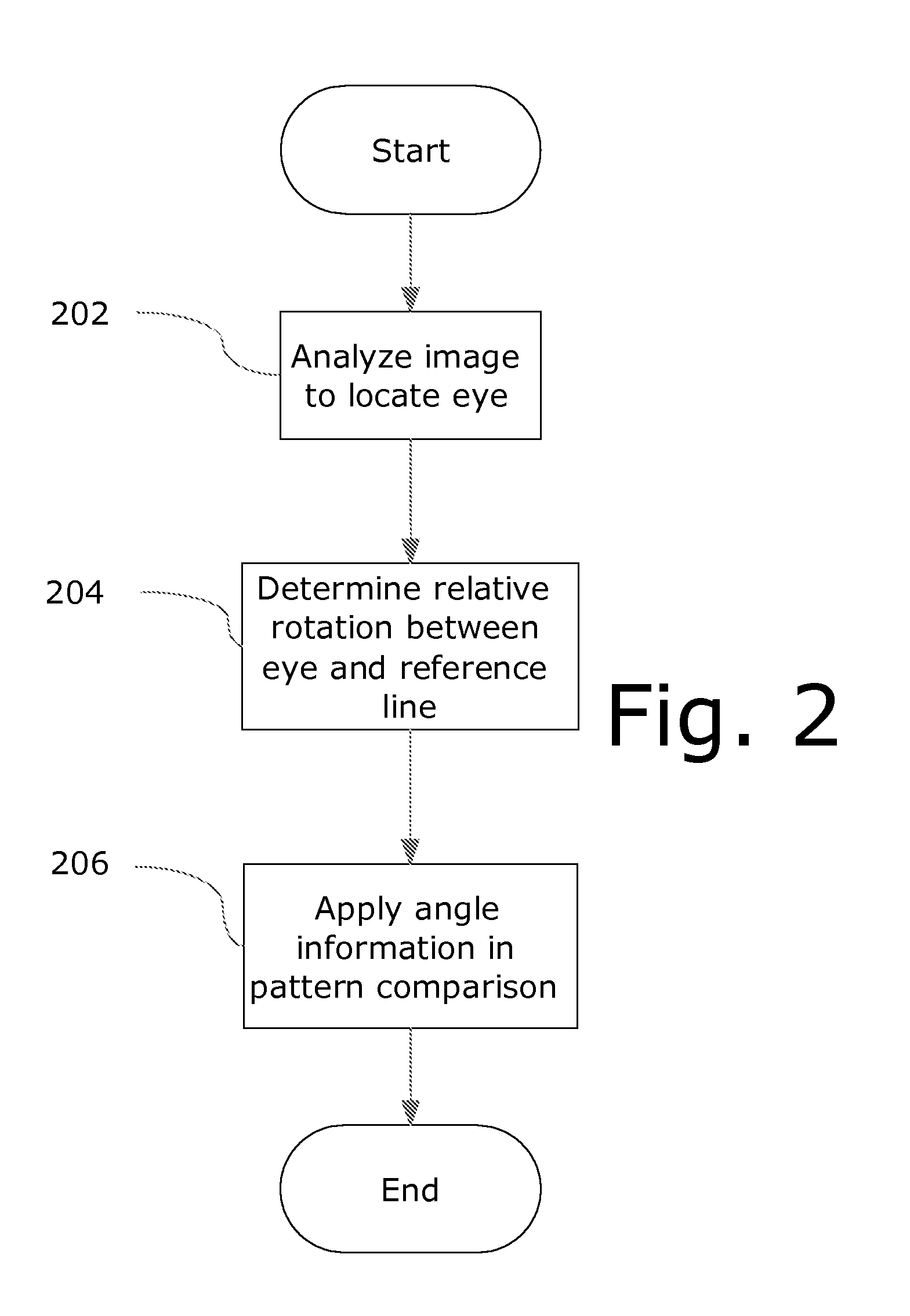
[0011]In a first example embodiment, an iris image is analyzed to determine the apparent angle of the eye in the image, relative to an arbitrarily selected reference axis (for example, a horizontal line passing through the center of the pupil image). Then, the image and/or pattern data extracted from the image is digitally rotated to normalize the angle relative to t

Problems solved by technology

If not dealt with, this relative angle between the pattern data sets will result in failure to find a match, although the two sets of pattern data are from the same eye.
This type of error is called a “false reject” and angular variations in imaging can potentially cause significant rates of false rejection.
However, there are disadvantages to this approach.
If the head is tilted by (for example) ten degrees in one of the images under comparison, no match will be found even though the irises are the same, resulting in a false reject.
With this traditional approach, there is a well-understood tradeoff between t

Method used


Image

  • Camera Angle Compensation in Iris Identification
  • Camera Angle Compensation in Iris Identification
  • Camera Angle Compensation in Iris Identification

Examples


Embodiment Construction

[0030]The present invention will be described in terms of one or more examples, with reference to the accompanying drawings. In the drawings, some like reference numbers indicate identical or functionally similar elements. Additionally, the left-most digit(s) of most reference numbers may identify the drawing in which the reference numbers first appear.

[0031]The present invention will be explained in terms of exemplary embodiments. This specification discloses one or more embodiments that incorporate the features of this invention. The disclosure herein will provide examples of embodiments, including examples of data analysis from which those skilled in the art will appreciate various novel approaches and features developed by the inventors. These various novel approaches and features, as they may appear herein, may be used individually, or in combination with each other as desired.

[0032]In particular, the embodiment(s) described, and references in the specification to “one embodime...


PUM


Abstract

An iris biometric image is analyzed to determine the apparent angle of the eye in the image, relative to an arbitrarily selected reference axis. The angle information is stored for use by the matching engine and/or the image data is modified to normalize the angle relative to the reference axis. In this manner, rotationally normalized data may be stored to facilitate future comparisons, and images obtained in real time may be used for iris identification in a matching engine that automatically compensates for angular variation.

Description

FIELD OF THE INVENTION[0001]The present invention is directed generally to the field of capturing and processing images for biometric iris identification.BACKGROUND[0002]Iris identification is recognized as one of the most user-friendly and accurate biometric technologies. Iris identification uses digital cameras to capture an image of the iris. Commercially available cameras are designed either to capture a single eye image or to simultaneously capture images of both irises.[0003]Iris identification is performed by matching pattern data extracted from a captured iris image to previously stored pattern data. Therefore, the angle of presentation of the iris in the image will affect the ability to match the image to a stored iris pattern. If the subject tilts his head or the eye is torsionally rotated within the subject's head while the image is being captured, or if a handheld camera is positioned at an angle relative to the person's head, the captured image will show the eye at an a...

Claims


Application Information

Patent Timeline
IPC IPC(8): G06K9/32G06T7/00
CPCG06K9/0061G06V40/193
Inventor YU, HSIANG-YISMITH, EVAN R
Owner EYE CONTROLS
Why Eureka
Try Eureka