
Eureka
For R&D, Eureka makes reading and utilizing patents & technical documents easy.
Eureka AIR
Designed for self-driven R&D workflows. Generate viable solutions, solve complex R&D challenges, empower your innovation with AI.

Eureka Materials
Designed for material experts only. Revolutionize your material R&D, from search, analyze, to developing new materials.

TechResearch
Generate reliable direction feasibility study reports for your R&D in just a few steps.

TechSeek
Discover and master advanced knowledge NOW. Basics, ideas, possibilities, all at once.

TechMind
As an expert in R&D Theories, TechMind can generates customized viable solutions instantly.

TechRisk
Analyze your overall solution with one click, know your potential R&D risks in advance.

TechMonitor
Get weekly tech updates, stay abreast of the latest tech innovations and key insights.
Image Processing Apparatus and Image Processing Method
- Summary
- Abstract
- Description
- Claims
- Application Information
AI Technical Summary
Problems solved by technology
Method used
Image

Examples
first embodiment
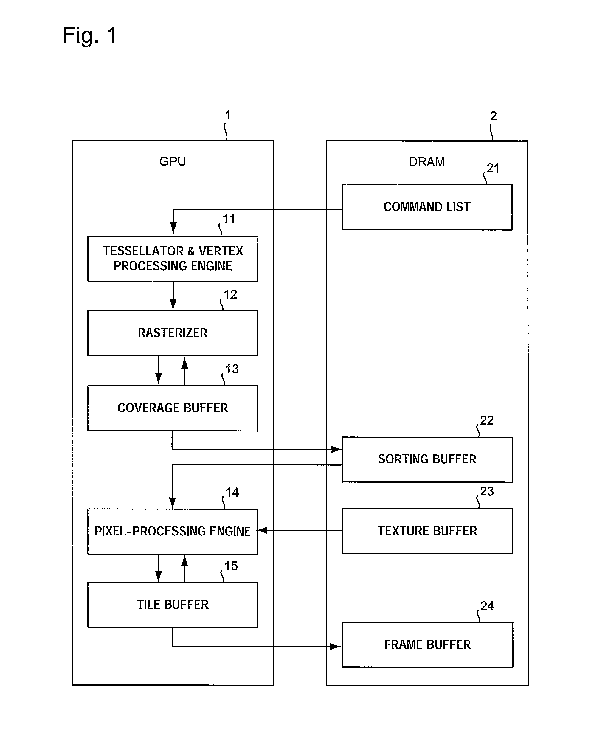
[0015]FIG. 1 is a block diagram illustrating the overall configuration of an image processing apparatus according to a first embodiment of the invention.
[0016]FIG. 1 shows that the image processing apparatus includes a graphics processing unit (GPU) 1 and a DRAM 2. The GPU 1 includes a tessellator and vertex-processing engine 11, a rasterizer 12, a coverage buffer 13, a pixel-processing engine 14, and a tile buffer 15. The DRAM 2 stores a command list 21 and includes a sorting buffer 22, a texture buffer 23, and a frame buffer 24.
[0017]If the command list 21 designates a curved line, the tessellator and vertex-processing engine 11 converts the curved line to vertices. The tessellator and vertex-processing engine 11 performs also the coordinate transformation of the vertices of the triangles representing figures. Examples of coordinate transformation of the vertices include those associated with the rotation, downscaling, and upscaling of figures formed with vertices. The rasterizer ...
second embodiment
[0030]FIG. 4 is a block diagram illustrating the overall configuration of an image processing apparatus according to a second embodiment of the invention.
[0031]FIG. 4 shows that the image processing apparatus includes a GPU 1′ instead of the GPU 1 shown in FIG. 1. The GPU 1′ includes a coverage buffer 13′ instead of the coverage buffer 13 shown in FIG. 1. The coverage buffer 13′ includes an overwrite determiner 12a, a drawing canceller 12b, and an information compressor 13a.
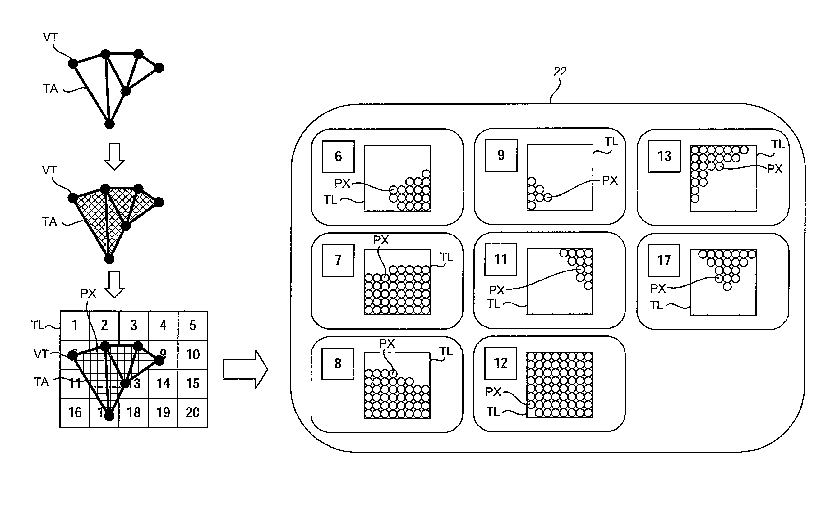
[0032]The overwrite determiner 12a determines whether or not there is a tile TL where all the pixels PX are to be overwritten by the object to be drawn next. The drawing canceller 12b abandons the pixel information of the other objects that has been registered thus far for the tile TL where all the pixels are to be overwritten by the object to be drawn next. In addition, the overwrite determiner 12a omits the storing of such pixel information in the sorting buffer 22. The information compressor 13a compresses th...
PUM
 Abstract
Description
Claims
Application Information
 - R&D Engineer
- R&D Manager
- IP Professional
- Industry Leading Data Capabilities
- Powerful AI technology
- Patent DNA Extraction
Browse by: Latest US Patents, China's latest patents, Technical Efficacy Thesaurus, Application Domain, Technology Topic, Popular Technical Reports.
© 2024 PatSnap. All rights reserved.Legal|Privacy policy|Modern Slavery Act Transparency Statement|Sitemap|About US| Contact US: help@patsnap.com