Optical fiber and method of manufacturing the same, end part processing method of optical fiber and optical fiber with ferrule

a technology of optical fiber and manufacturing method, which is applied in the field of optical fiber and a manufacturing method, and an end part processing method of optical fiber, and an optical fiber with a ferrule, can solve the problems of higher manufacturing cost, affecting the service life of optical fibers, so as to reduce the inner diameter and facilitate splicing

Inactive Publication Date: 2011-06-16
HITACHI METALS LTD
View PDF10 Cites 14 Cited by
  • Summary
  • Abstract
  • Description
  • Claims
  • Application Information

AI Technical Summary

Benefits of technology

[0064]The present invention is able to provide an optical fiber that permits, even when the cladding outer diameter thereof is smaller than 125 μm, an eased splicing with other optical fiber using a general-purpose ferrule without relying on such a special ferrule as has an insertion hole for inserting an optical fiber having a reduced inner diameter and a method of manufacturing the same; an end part processing method of an optical fiber; and an optical fiber with a ferrule.

Problems solved by technology

However, the special ferrule like that having a small sized inner diameter of the insertion hole for inserting the optical fiber has problems in a practical use because such a ferrule is not an easily-workable item and incurs a higher manufacturing cost.
This brings a concern that application of optical fibers, such as holey fibers, having a cladding outer diameter smaller than 125 μm to a wiring system in the subscriber premises or the inside of equipment may be disturbed.
However, applying a jacket over an optical fiber of which cladding outer diameter is smaller than 125 μm precisely without eccentricity of wall thickness of the jacket to obtain an optical fiber having an outer diameter of 125 μm requires a highly sophisticated manufacturing technique and invites a problem of cost increase in manufacturing.
Further, when the jacket wall thickness is not uniform, there arises a concern that splice loss may increase, because such irregularity at the joining point with other optical fiber will cause deviation of the optical axis.

Method used


Image

  • Optical fiber and method of manufacturing the same, end part processing method of optical fiber and optical fiber with ferrule
  • Optical fiber and method of manufacturing the same, end part processing method of optical fiber and optical fiber with ferrule
  • Optical fiber and method of manufacturing the same, end part processing method of optical fiber and optical fiber with ferrule

Examples


modification example

of Present Invention

[0111]As for the adhesive to be used in the embodiment, it is preferable to use a thermosetting resin of low viscosity or such an instant adhesive as is applicable to installing ferrules (Trade product code: AT8816; NTT Advanced Technology Corp.) to prevent involving bubbles inside the ferrule.

[0112]In the embodiment, the explanation has taken a ferrule for a single-fiber connector as an explanatory example; it is also feasible to apply the invention to multi-fiber ferrules such as for MT connectors and MPO connectors. However, when an aligning type fusion splicer is used, it is preferable to make fusion splice separately for each of optical fibers one by one.

Effect of Embodiments

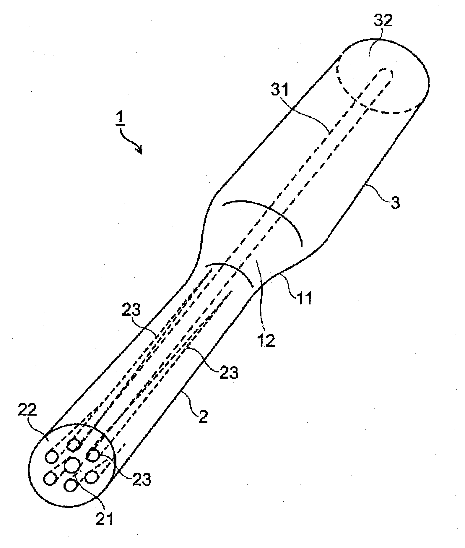
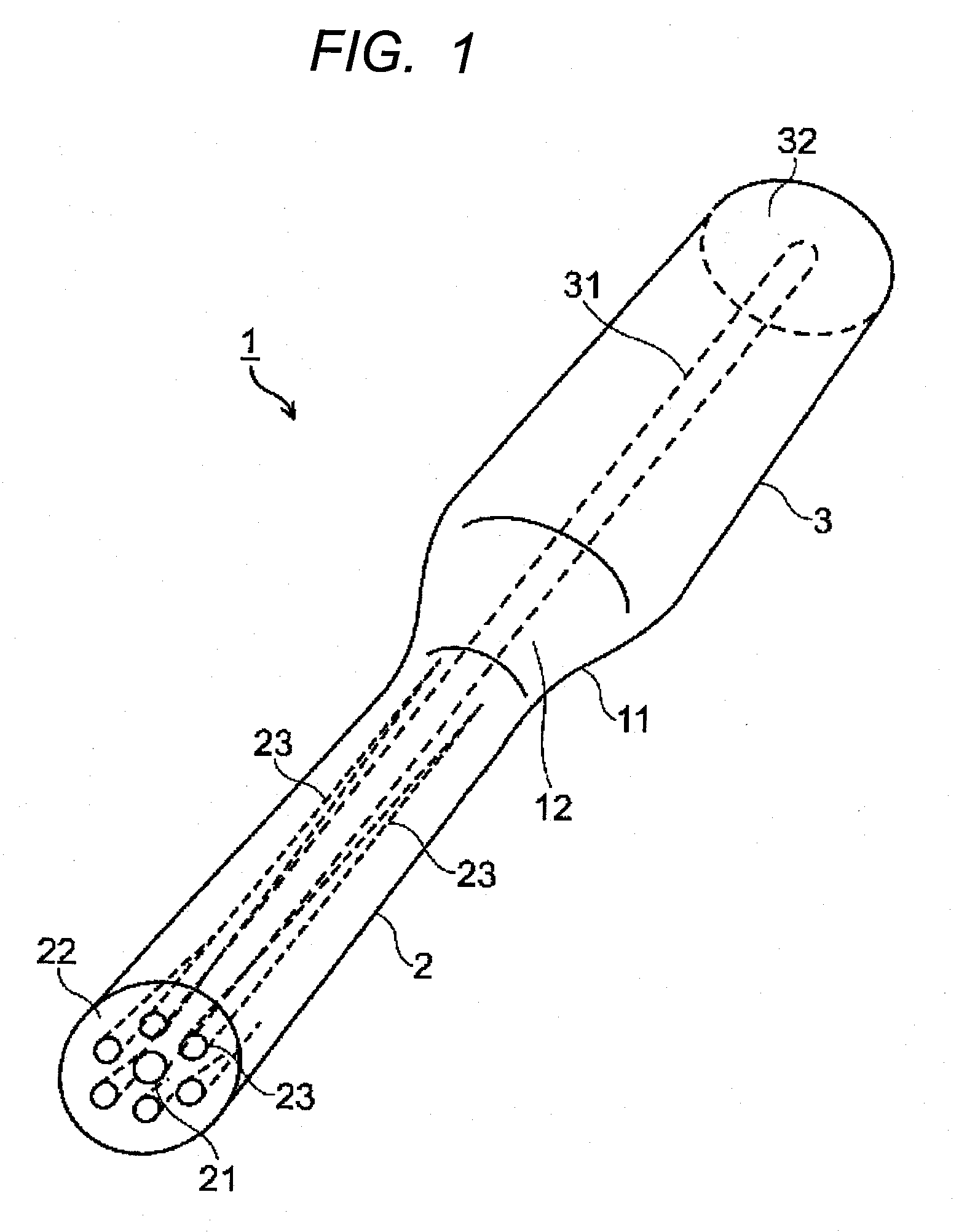
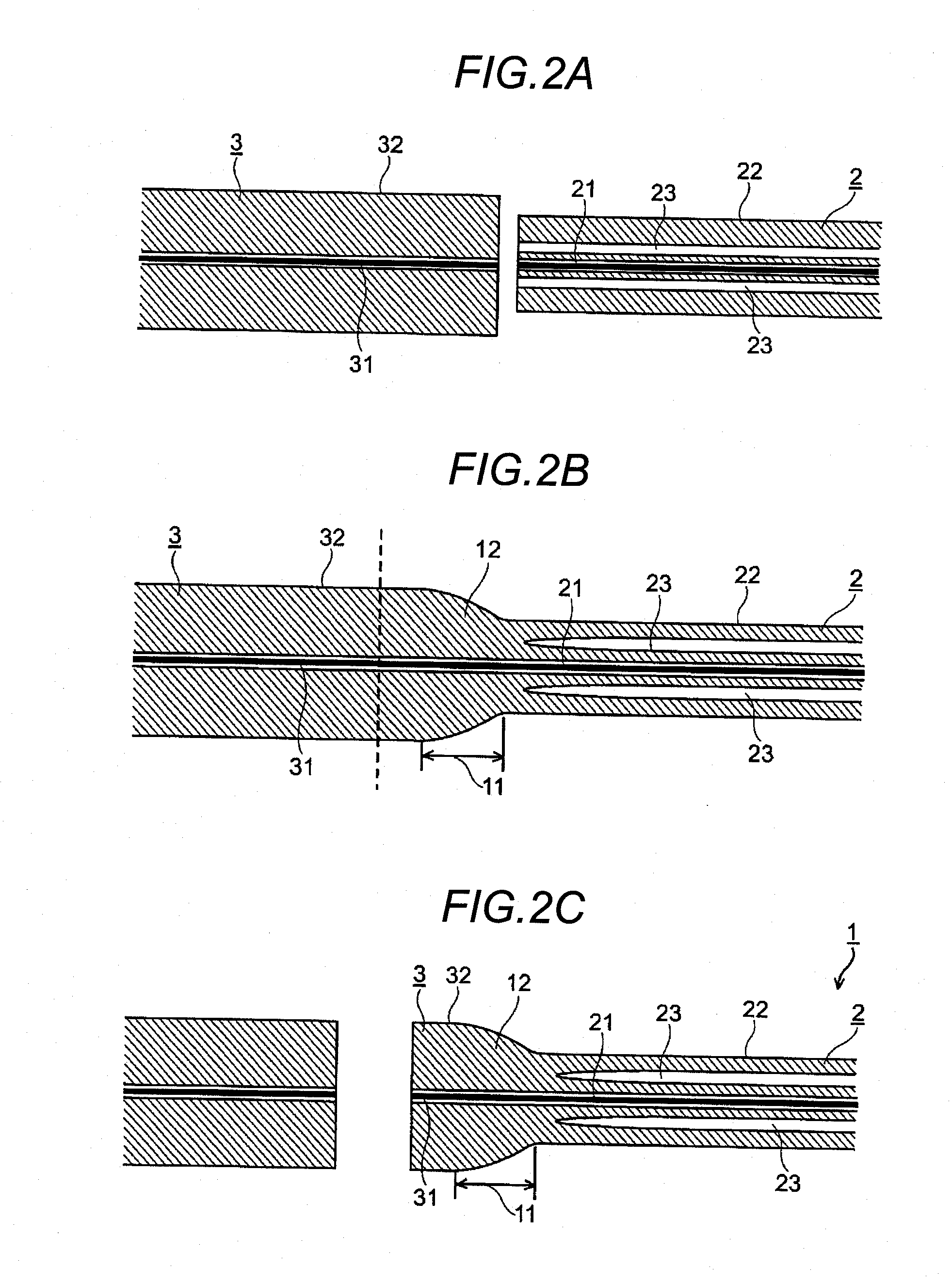
[0113]In the embodiments stated above, the optical fiber has such a configuration that the end of a holey fiber having an outer diameter smaller than 125 μm is fusion-spliced to a single-mode fiber having an outer diameter larger than the holey fiber. Therefore, a general-purpose ferrule...


PUM


Abstract

An optical fiber that permits, even when the cladding outer diameter thereof is smaller than 125 μm, an eased splicing with other optical fiber using a general-purpose ferrule, is provided. The optical fiber comprises: a first optical fiber having a first core and a first cladding having a cladding outer diameter smaller than 125 μm, wherein the first cladding has a plurality of air holes that extend longitudinally along the axis of the first core; a second optical fiber having a second core to be spliced to the first core, and a second cladding having a cladding outer diameter larger than the outer diameter of the first cladding, wherein the second cladding is to be spliced to the first cladding; and a fusion splice formed between the end of the first optical fiber and the end of the second optical fiber by fusion.

Description

TECHNICAL FIELD[0001]The present invention relates to an optical fiber and a method of manufacturing the same, and an end part processing method of an optical fiber, and an optical fiber with a ferrule; the invention particularly relates to an optical fiber, which is suitable for such as an optical fiber cord for communication and an optical device, and a method of manufacturing the same, and an end part processing method of an optical fiber, and an optical fiber with a ferrule.BACKGROUND OF THE INVENTION[0002]In recent years, new types of optical fibers, called holey fibers (HFs) and photonic crystal fibers (PCFs), have attracted attention. (See Non-patent Literature 1 for example.)[0003]A typical construction of holey fibers is illustrated in FIG. 7. As illustrated in FIG. 7, a holey fiber 102 is comprised of a core 121 and cladding 122 formed around the core 121, wherein the cladding 122 has a plurality of air holes 123 that extends longitudinally along the axis of the core 121.[...

Claims


Application Information

Patent Timeline
Patent Type & Authority Applications(United States)
IPC IPC(8): G02B6/255G02B6/38
CPCG02B6/2552G02B6/2551
Inventor TACHIKURA, MASAOOHSONO, KAZUMASASHIINA, NORIBUMINAMEKAWA, YOSHIKAZU
Owner HITACHI METALS LTD
Why Eureka
Try Eureka