Hydraulic control equipment and control method of clutch

A technology for controlling equipment and clutches, used in mechanical equipment, transmission control, components with teeth, etc., can solve problems such as impact, generator rotor damage, etc., to reduce impact force, avoid damage, and connect reliably and stably. Effect

Pending Publication Date: 2021-04-13
哈尔滨通用液压机械制造有限公司
View PDF0 Cites 0 Cited by
  • Summary
  • Abstract
  • Description
  • Claims
  • Application Information

AI Technical Summary

Problems solved by technology

[0004] The purpose of the present invention is to solve the problem that the gearbox of the existing barring drive device will be impacted during the process of shifting speed with the clutch, which will cause damage to the generator rotor

Method used


Image

  • Hydraulic control equipment and control method of clutch
  • Hydraulic control equipment and control method of clutch
  • Hydraulic control equipment and control method of clutch

Examples


Embodiment Construction

[0039] In order to make the above objects, features and advantages of the present invention more comprehensible, specific embodiments of the present invention will be described in detail below in conjunction with the accompanying drawings.

[0040] In the description of the present invention, it should be understood that the orientation or positional relationship indicated by the terms "upper", "lower", "front", "rear" etc. is based on the orientation or positional relationship shown in the drawings, and is only for It is convenient to describe the present invention and simplify the description, but does not indicate or imply that the device or element referred to must have a specific orientation, be constructed and operate in a specific orientation, and thus should not be construed as limiting the present invention.

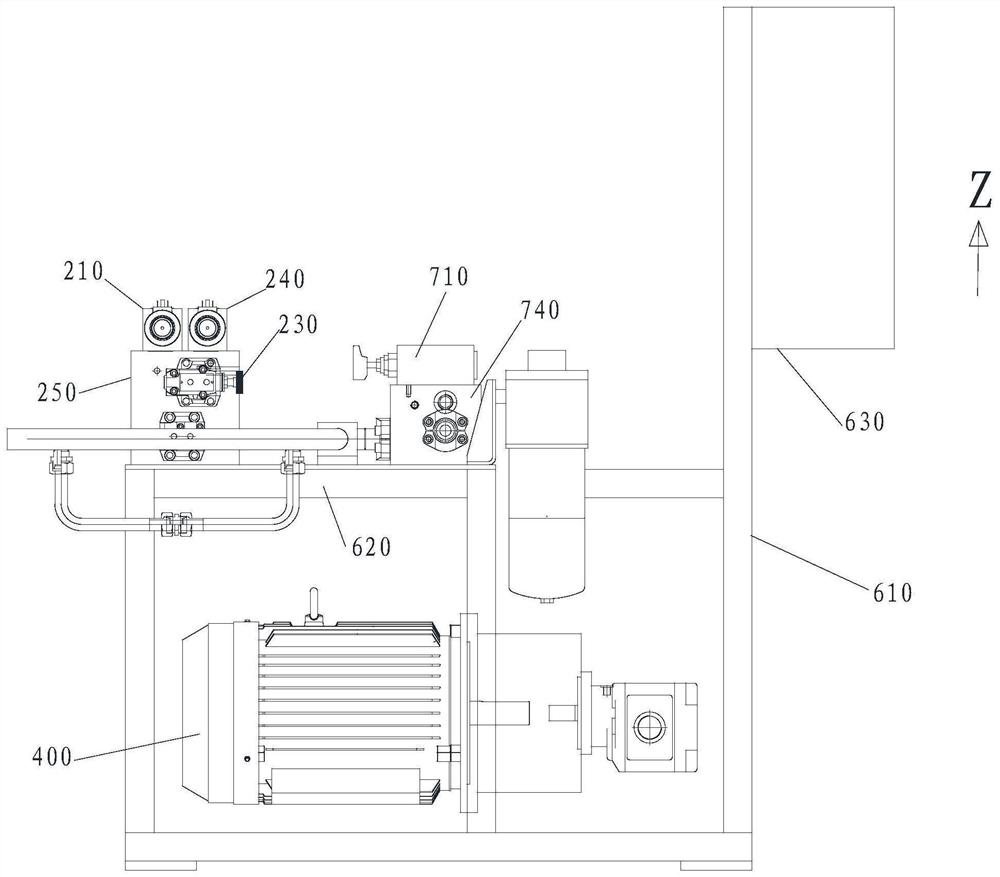
[0041] Moreover, the Z axis in the accompanying drawings represents the vertical direction, that is, the up and down position, and the positive direction of the ...


PUM


Abstract

The invention provides hydraulic control equipment and a control method of a clutch, and particularly relates to the technical field of generators. The hydraulic control equipment of the clutch comprises a first reversing valve, a first pressure reducing valve, a second pressure reducing valve and a second reversing valve, wherein the first reversing valve is used for controlling the hydraulic oil to enter and exit the clutch; the first pressure reducing valve is arranged in a first pipeline, the first pipeline is in communication with the first reversing valve, and the first pipeline is a one-way flowing pipeline; the second pressure reducing valve is arranged in a second pipeline, the second pipeline is in communication with the first reversing valve, and the flow direction of the second pipeline only leads to the first reversing valve; the second reversing valve is in communication with the first pipeline and the second pipeline, and the second reversing valve is used for enabling high-pressure hydraulic oil to selectively enter the first pipeline or the second pipeline; and the set passing pressure value of the first pressure reducing valve is higher than the set passing pressure value of the second pressure reducing valve, and the clutch is a friction type clutch.

Description

technical field [0001] The invention relates to the technical field of generators, in particular to a clutch hydraulic control device and control method. Background technique [0002] The generator of the existing power plant needs to drive the rotor of the generator to rotate under the action of external force, so as to generate electricity and generate electric energy, and the generator needs to be stopped, that is, the rotor of the generator stops rotating, so as to carry out regular maintenance. Afterwards, it is necessary to crank the generator through the hydraulic cranking device to detect and judge whether the load driven by the rotor is stuck and the resistance increases, and also through this method, the gearbox of the hydraulic cranking device Different transmission shafts are connected or disengaged from the corresponding friction clutches to realize the speed change of the gearbox, so as to detect various operating states of the generator rotor. [0003] Howeve...

Claims


Application Information

Patent Timeline
Patent Type & Authority Applications(China)
IPC IPC(8): F16H61/04F16H61/02
CPCF16H61/0267F16H61/04F16H2061/0407
Inventor 王龙王利明
Owner 哈尔滨通用液压机械制造有限公司
Why Eureka
Try Eureka