Water-proof sound-transmitting membrane, method for producing the water-proof sound-transmitting membrane, and electrical appliance including the water-proof sound-transmitting membrane

a sound-transmitting membrane and sound-transmitting technology, which is applied in the direction of transducer diaphragms, electrical apparatus casings/cabinets/drawers, separation processes, etc., can solve the problems of increased surface density, membrane may be damaged, and membrane tends to rupture easily

Active Publication Date: 2011-06-16
NITTO DENKO CORP
View PDF21 Cites 44 Cited by
  • Summary
  • Abstract
  • Description
  • Claims
  • Application Information

AI Technical Summary

Benefits of technology

[0012]Secondly, since the water-proof sound-transmitting membrane usually is attached to an opening provided to a housing of an electrical appliance, a surface of the membrane is exposed to the outside. Thus, the membrane may be damaged by contact with foreign matters from the outside. When the membrane is damaged, the waterproofness is lost. Moreover, even when, although the membrane is not damaged, the surface of the membrane is scratched or the membrane is deformed, the water leakage and rupture of the membrane start from that area more easily when water pressure is applied thereto. This tendency becomes obvious particularly when the surface density of the water-proof sound-transmitting membrane is reduced in order to secure the sound transmittance. Thus, the puncture strength of the membrane is an important factor in coping with the contact of the foreign matters from the outside. When the surface density of the membrane is increased, the puncture strength also is increased. However, the increased surface density lowers the sound transmittance as described above.
[0016]The electrical appliance of the present invention is an electrical appliance with a sound function, including: at least one selected from a sound emitting part for outputting sound and a sound receiving part for inputting sound; and a water-proof sound-transmitting membrane that allows sound to be transmitted between the sound emitting part and outside and / or between the sound receiving part and the outside, and suppresses entry of water into the sound emitting part and / or the sound receiving part. The water-proof sound-transmitting membrane is the water-proof sound-transmitting membrane of the present invention.
[0017]As described above, in order to achieve both the high levels of waterproofness and sound transmittance of the water-proof sound-transmitting membrane including the PTFE porous membrane, it is necessary to reduce the average pore diameter and surface density of the PTFE porous membrane, and furthermore, to increase the tensile strength and puncture strength of the membrane while keeping the surface density low.
[0019]One method for increasing the strength of the PTFE porous membrane while keeping the surface density low is to increase the stretching ratio of the membrane. This is because in the PTFE porous membrane, the orientation of PTFE molecules tends to grow when the stretching ratio is increased, leading to a higher matrix strength. Thus, when a comparison is made between a membrane with a low stretching ratio and a membrane with a high stretching ratio, the latter has a higher strength even when they have the same surface density as each other.

Problems solved by technology

Firstly, when a high water pressure is applied to the water-proof sound-transmitting membrane for a certain period of time or longer because the water-proof sound-transmitting membrane is immersed in water, the water pressure stretches the membrane.
As a result, micropores of the membrane are deformed, allowing water to permeate through the membrane, and the membrane tends to rupture easily.
However, the increased surface density lowers the sound transmittance as described above.
However, even when the water pressure is lower than the high pressure, a similar phenomenon occurs in some cases where the membrane is under water pressure for a long time.
Secondly, since the water-proof sound-transmitting membrane usually is attached to an opening provided to a housing of an electrical appliance, a surface of the membrane is exposed to the outside.
Thus, the membrane may be damaged by contact with foreign matters from the outside.
When the membrane is damaged, the waterproofness is lost.
Moreover, even when, although the membrane is not damaged, the surface of the membrane is scratched or the membrane is deformed, the water leakage and rupture of the membrane start from that area more easily when water pressure is applied thereto.
However, the increased surface density lowers the sound transmittance as described above.

Method used


Image

  • Water-proof sound-transmitting membrane, method for producing the water-proof sound-transmitting membrane, and electrical appliance including the water-proof sound-transmitting membrane
  • Water-proof sound-transmitting membrane, method for producing the water-proof sound-transmitting membrane, and electrical appliance including the water-proof sound-transmitting membrane
  • Water-proof sound-transmitting membrane, method for producing the water-proof sound-transmitting membrane, and electrical appliance including the water-proof sound-transmitting membrane

Examples


example 1

[0111]100 parts by weight of a PTFE fine powder (Polyflon F101HE produced by Daikin Industries Ltd.) and 20 parts by weight of a liquid lubrication agent (naphtha) were kneaded uniformly to prepare a paste containing the PTFE fine powder and naphtha. This paste was preformed into a circular cylindrical shape at 20 kg / cm2. Next, the obtained circular cylindrical preformed product was extrusion-molded to obtain a sheet-shaped molded product. The obtained sheet-shaped molded product was measured for tensile strength (the distance between chucks was 10 mm and the width of the sample was 10 mm in the measurement). As a result, the tensile strength was 1.8 MPa both in the longitudinal direction (MD) and the width direction (TD).

[0112]Subsequently, while containing the liquid lubrication agent, the sheet-shaped molded product was made go through between a pair of metal pressure rolls to form a long sheet with a thickness of 200 μm. The long sheet continuously was made pass through a dryer ...

example 2

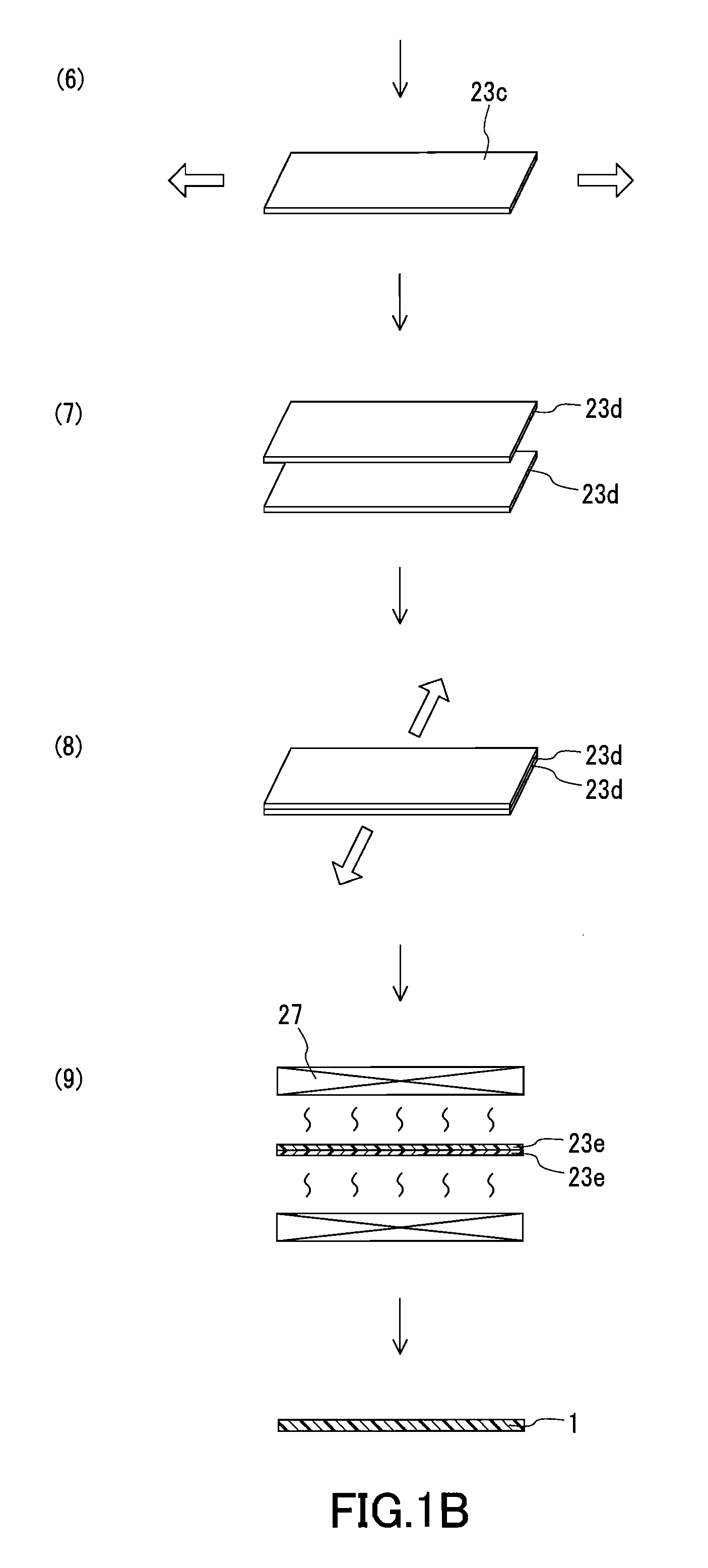
[0115]The PTFE sheet produced in Example 1 was stretched 8 times in the longitudinal direction in the dryer at an ambient temperature of 290° C. Furthermore, two of the PTFE sheets that had been stretched in the longitudinal direction were stacked and stretched 31.5 times in the width direction at an ambient temperature of 150° C. by the tenter method. Then, the biaxially-stretched PTFE sheets were sintered. Thus, a PTFE porous membrane with a dual-layer structure was obtained.

example 3

[0116]The PTFE sheet produced in Example 1 was stretched 10 times in the longitudinal direction in the dryer at an ambient temperature of 290° C., and further was stretched 60 times in the width direction at an ambient temperature of 150° C. by the tenter method. Then, three of the biaxially-stretched PTFE sheets were stacked and sintered. Thus, a PTFE porous membrane with a three-layer structure was obtained.


PUM

PropertyMeasurementUnit
pore diameteraaaaaaaaaa
tensile strengthaaaaaaaaaa
pressureaaaaaaaaaa

Abstract

The present invention provides a water-proof sound-transmitting membrane including a polytetrafluoroethylene (PTFE) porous membrane, in which the waterproofness is enhanced further with little lowering of the sound transmittance. The water-proof sound-transmitting membrane includes the PTFE porous membrane. The PTFE porous membrane includes a first porous layer, and a second porous layer stacked on and integrated with the first porous layer by a binding force acting between PTFE matrices. The first porous layer and the second porous layer each are composed of PTFE with a number-average molecular weight of 5.0×10⁷ or more determined by a standard specific gravity method. At least one layer selected from the first porous layer and the second porous layer has an average pore diameter of 1 μm or less. The water-proof sound-transmitting membrane has a surface density of 1 g / m2 to 10 g / m2.

Description

BACKGROUND OF THE INVENTION[0001]1. Field of the Invention[0002]The present invention relates to a water-proof sound-transmitting membrane to be used for electrical appliances with a sound function, and a method for producing the water-proof sound-transmitting membrane. The present invention also relates to an electrical appliance including the water-proof sound-transmitting membrane.[0003]2. Description of Related Art[0004]Electrical appliances, such as cellular phones, notebook computers, electronic notebooks, digital cameras, and game machines, are desired to have a water-proof structure because they often are used outdoors. Parts that are most difficult to have the water-proof structure in an electrical appliance are a sound emitting part and a sound receiving part, such as a speaker, a microphone, and a buzzer. Generally, a housing of the electrical appliance with the sound function has openings at positions corresponding to the sound emitting part and the sound receiving part....

Claims


Application Information

Patent Timeline
Patent Type & Authority Applications(United States)
IPC IPC(8): G10K13/00B32B37/14B32B38/00B32B38/12B32B3/26
CPCB32B5/32B32B27/00H04R2307/025H04R2231/001H04R31/003B32B27/322B32B2250/246B32B2264/0257B32B2305/026B32B2305/80B32B2307/10B32B2307/54B32B2307/558B32B2307/7265B32B27/06B32B5/22B01D71/36
Inventor HORIE, YURIABE, YUUICHIFURUUCHI, KOUJITAKIISHI, KOUSEI
Owner NITTO DENKO CORP
Why Eureka
Try Eureka