Injector control for fuel cell system

Active Publication Date: 2011-06-16
GM GLOBAL TECH OPERATIONS LLC
View PDF4 Cites 11 Cited by
  • Summary
  • Abstract
  • Description
  • Claims
  • Application Information

AI Technical Summary

Benefits of technology

[0013]In accordance with the teachings of the present invention, a fuel cell system is disclosed that employs an injector/ejector for providing fresh hydrogen and anode recirculation gas to the anode side of a fuel cell stack. The injector/ejector is operated with a variable frequency so that the injector open time at low stack current densities is long enough to allow a pressure drop to

Problems solved by technology

MEAs are relatively expensive to manufacture and require certain conditions for effective operation.
An improper anode flow and pressure to the fuel cell stack could result in a low anode flow rate that may allow water to accumulate in the anode flow channels.
Accumulation of water in the anode flow channels may cause anode flow to be diverted to other channels where those channels feeding certain fuel cells in the stack are starved of hydrogen, and may experience a voltage collapse.
If enough recirculation gas is not provided, then the flow rate may not be high enough to drive out excess water in the anode flow channels.
The lower the current density of the stack, the lower the anode flow rate, and thus the more likely the stack will be flooded with water.
An improper anode flow and pressure to the fuel cell stack could also result in a low anode flow rate that may not provide hydrogen gas to each fuel cell in the stack.
Tolerances in material properties might cause a higher pressure drop for some of the fuel cells, thus reducing the amount of gas supplied to an individual fuel cell.
If enough recirculation gas is not provided, then the flow rate may not be high enough to supply sufficient hydrogen gas to the fuel cells with a higher individual pressure drop.
Although this is long enough to supply the proper amount of hydrogen for the fuel cell reaction, it may be too short to build up a pressure drop across the anode side of the fuel cell stack to achieve a high enough gas velocity throughout the fuel cell stack.

Method used


Image

  • Injector control for fuel cell system
  • Injector control for fuel cell system
  • Injector control for fuel cell system

Examples


Embodiment Construction

[0019]The following discussion of the embodiments of the invention directed to a method for changing the frequency command to an injector / ejector that provides anode recirculation gas to the anode side of a fuel cell stack is merely exemplary in nature, and is in no way intended to limit the invention or its applications or uses.

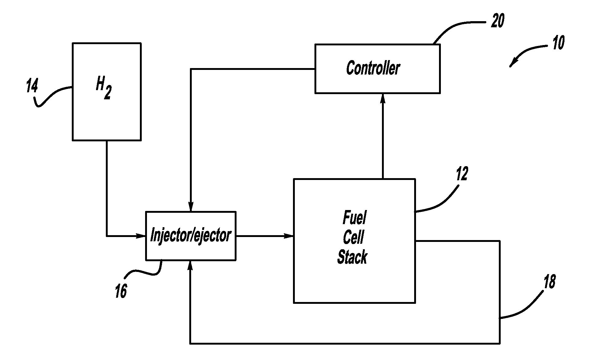
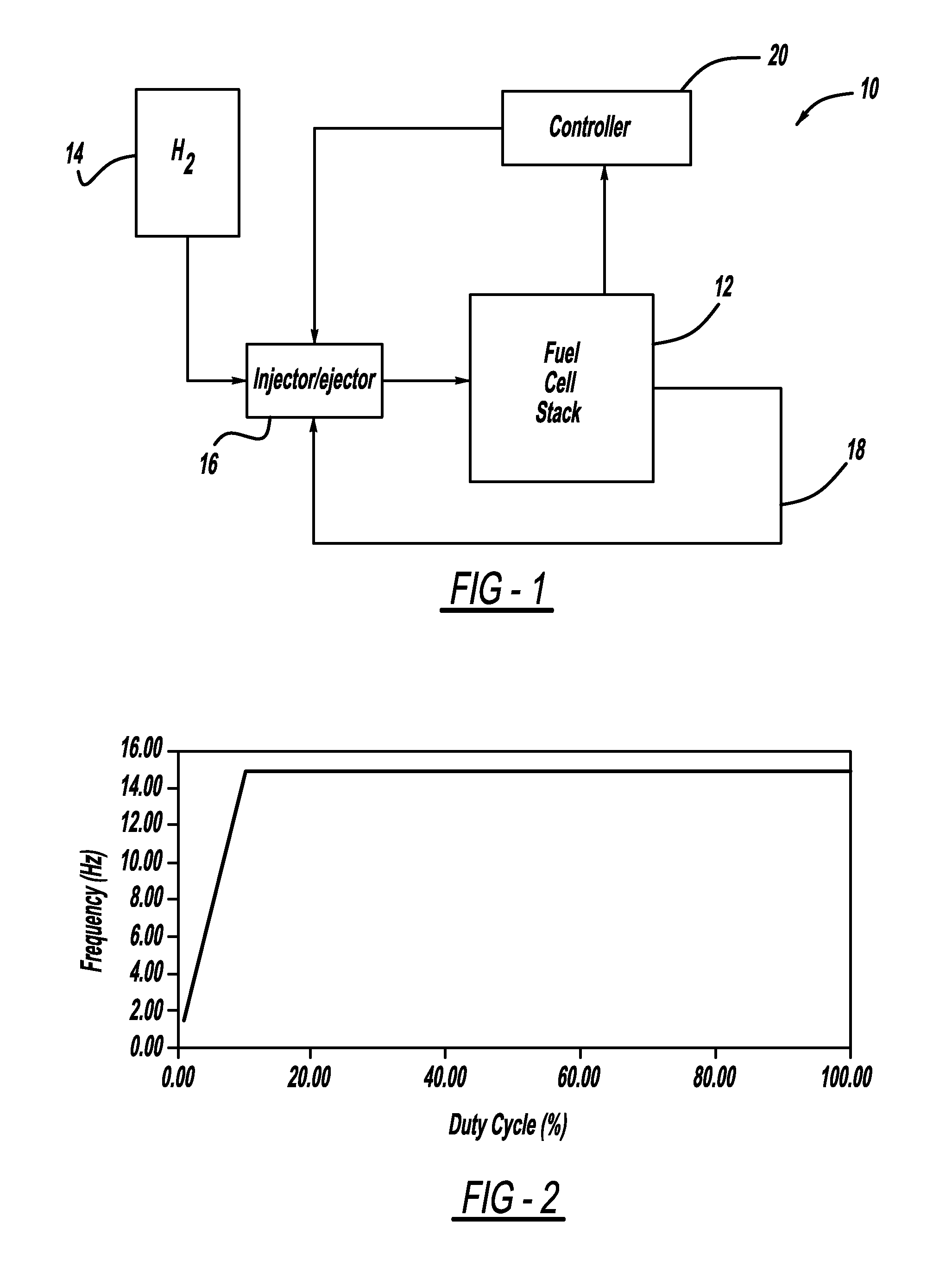
[0020]FIG. 1 is a block diagram of a fuel cell system 10 including a fuel cell stack 12. A hydrogen gas source 14 provides hydrogen gas to the anode side of the fuel cell stack 12 through an injector / ejector 16. Anode exhaust gas is output from the fuel cell stack 12 on anode recirculation line 18 that returns the anode exhaust gas to the injector / ejector 16. As discussed above, the injector / ejector 16 is a known device that has a duty cycle that provides a flow of hydrogen gas from the source 14 when the injector / ejector 16 is open and cuts off the flow of hydrogen gas to the fuel cell stack 12 when the injector / ejector 16 is closed. When the injector / eject...


PUM


Abstract

A fuel cell system that employs an injector / ejector for providing fresh hydrogen and anode recirculation gas to the anode side of a fuel cell stack. The injector / ejector is operated with a variable frequency so that the injector open time at low stack current densities is long enough to allow a pressure drop to be provided in the anode flow channels to push out water that may have accumulated therein. In one embodiment, the injector / ejector control provides a minimum pulse width per cycle and a maximum frequency so that as the stack current density decreases below a certain value the frequency decreases from the maximum frequency to maintain the pulse width constant at the minimum pulse width.

Description

BACKGROUND OF THE INVENTION[0001]1. Field of the Invention[0002]This invention relates generally to a system and method for efficiently providing anode recirculation to a fuel cell stack and, more particularly, to a system and method for efficiently providing anode recirculation gas to the anode side of the fuel cell stack using an injector / ejector.[0003]2. Discussion of the Related Art[0004]Hydrogen is a very attractive fuel because it is clean and can be used to efficiently produce electricity in a fuel cell. A hydrogen fuel cell is an electro-chemical device that includes an anode and a cathode with an electrolyte therebetween. The anode receives hydrogen gas and the cathode receives oxygen or air. The hydrogen gas is dissociated in the anode to generate free protons and electrons. The protons pass through the electrolyte to the cathode. The protons react with the oxygen and the electrons in the cathode to generate water. The electrons from the anode cannot pass through the elect...

Claims


Application Information

Patent Timeline
IPC IPC(8): H01M8/00H01M8/04
CPCH01M8/04097H01M8/04388Y02E60/50H01M8/04753H01M8/04589
Inventor SENNER, RALFDI FIORE, DANIEL C.
Owner GM GLOBAL TECH OPERATIONS LLC
Why Eureka
Try Eureka