
Socket and Contact Having Anchors

a technology applied in the field of sockets and contacts, can solve the problems of various deficiencies in the conventional testing of burn-in sockets and electrical contacts used in such sockets, and achieve the effect of precise and accurate manner

Inactive Publication Date: 2011-06-16
SENSATA TECH MASSACHUSETTS INC
View PDF22 Cites 3 Cited by
  • Summary
  • Abstract
  • Description
  • Claims
  • Application Information

AI Technical Summary

Benefits of technology

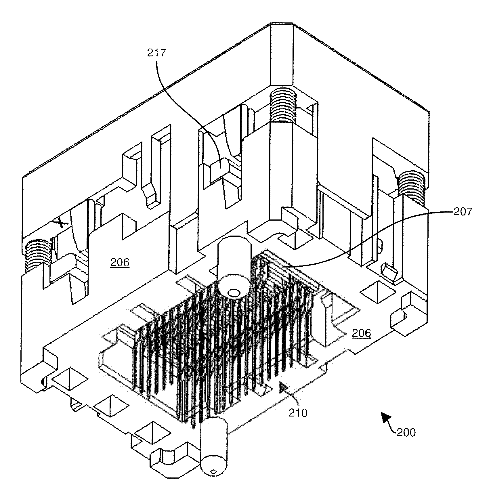
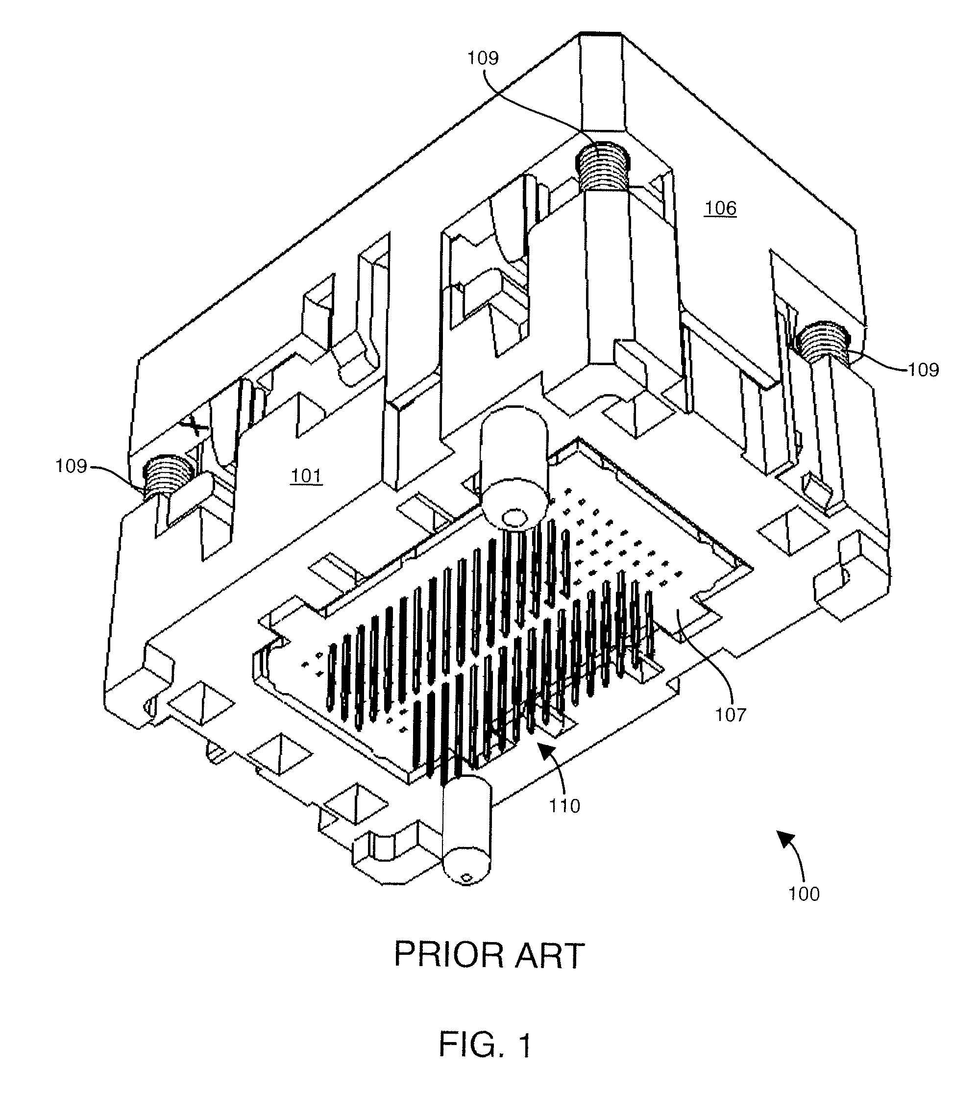
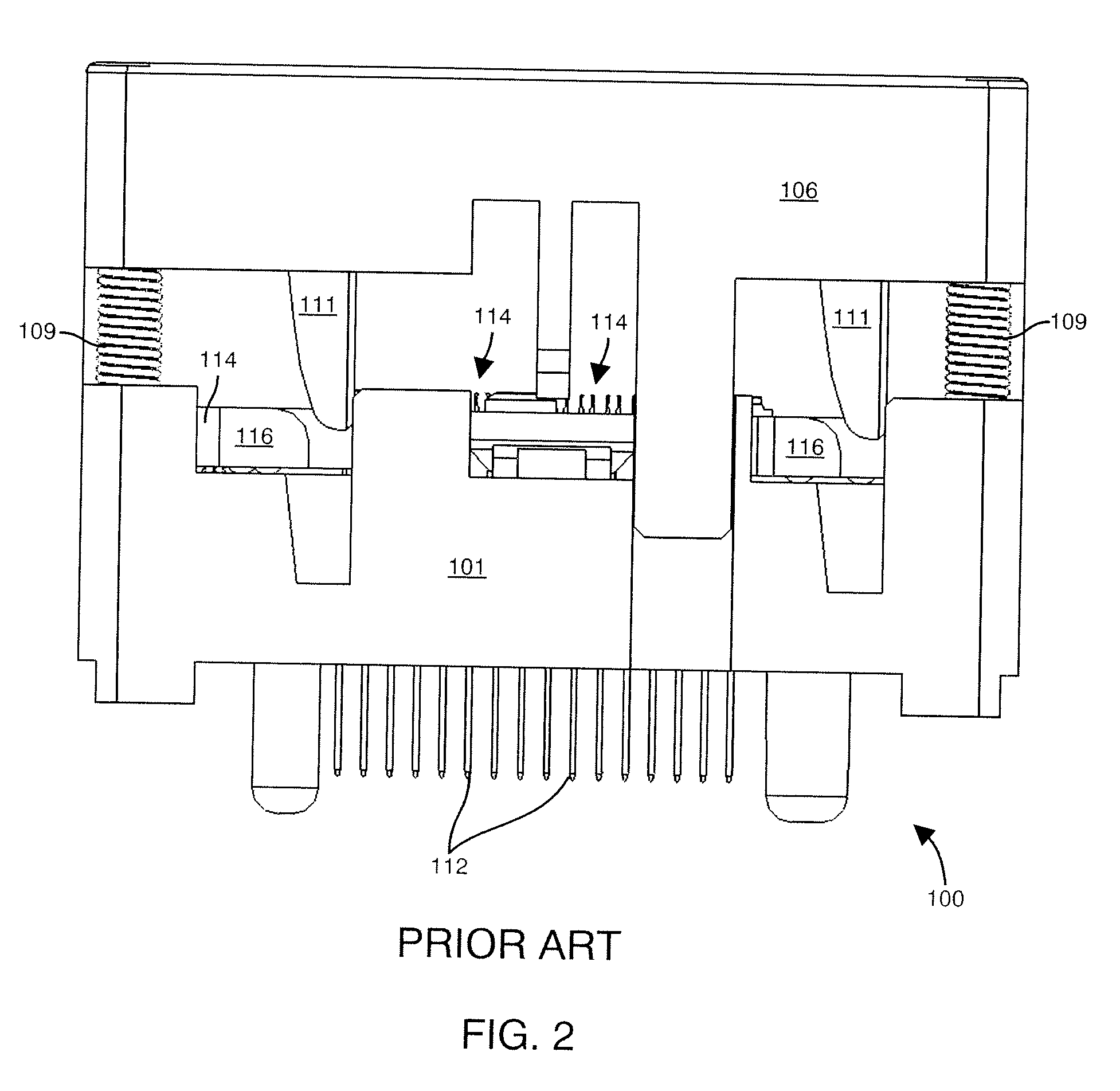
[0012]During manufacturing each contact finger 114 of the contact 110 must be accurately aligned and then inserted into a respective finger slot formed in the contact cavity 108 within the body 101 of the socket 100. The finger slots 108 for each contact finger 114 are part of the contact cavity that is integrally formed in the body 101 of the socket 100. Once each contact 110 is fully inserted into the body 101, to keep the lead ends 112 of each contact 110 properly aligned, conventional sockets 100 include the alignment plate 107 that inserts over the lead ends of each contact 110 in the array of contacts to properly maintain alignment of each contact lead 112. The alignment plate 107 maintains proper alignment of each contact 110 and counteracts forces exerted on the contact 110 during insertion and during normal opening and closing of contact fingers.
[0013]In contrast to conventional socket and contact designs, embodiments disclosed herein provide for a contact and body portion of a socket that does not require a separate alignment plate 107 to be used to maintain alignment of each contact in a socket. By not requiring the alignment plate, cost per part and assembly time are reduced. Embodiments disclosed herein include a socket having a base portion defining an array of contact cavities. The base portion includes a top side and a bottom side and a plurality of ribs extending from the bottom side. Each rib defines at least one sidewall that engages with an anchor of a contact to securely mount the contact within a contact cavity that receives the contact. A plurality of newly designed contacts are inserted into the array of contact cavities defined in the base portion. Each contact includes a mounting portion preferably having a first anchor and a second anchor extending from the mounting portion. The anchors are operable to engage the ribs of the base portion to securely mount the contact. The first anchor provides a first anchor force for the contact to the base portion that is substantially greater than a second anchor force provided by the second anchor to the base portion.

Problems solved by technology

Conventional testing of burn-in sockets as well as the electrical contacts used in such sockets suffer from various deficiencies.

Method used


Image

  • Socket and Contact Having Anchors
  • Socket and Contact Having Anchors
  • Socket and Contact Having Anchors

Examples


Embodiment Construction

[0030]Embodiments of the invention disclosed herein provide for a novel socket and contact for use in IC testing that provides secure mounting or fitment of contacts into the socket without a requirement for an alignment plate. From the discussion above of the conventional sockets, an alignment plate is required to be inserted on the underside of a conventional socket body to maintain alignment of the contact leads. The embodiments disclosed herein include a newly designed socket body that includes mounting ribs that extend below a lower surface of the socket body to provide additional contact support. Additionally, embodiments include a newly designed contact that includes a mounting area with protrusions or anchors that allow the mounting area to firmly grip the ribbed sidewalls of the socket body to firmly hold the newly designed contact into the cavity without requiring an alignment plate. The anchors provide a gripping force to more securely adhere the mounting portion of the c...


PUM


Abstract

A socket apparatus comprises a base portion defining an array of contact cavities. A plurality of contacts are inserted into the array of contact cavities defined in the base portion. The base portion includes a top side and a bottom side and a plurality of ribs extending from the bottom side. Each rib defines at least one sidewall that engages with an anchor of a contact to securely mount the contact. Each contact includes a mounting portion having a first anchor and a second anchor extending from the mounting portion and operable to engage a mounting surface of the base portion to securely mount the contact. The first anchor provides a first anchor force for the contact to the base portion that is substantially greater than a second anchor force provided by the second anchor to the base portion.

Description

FIELD OF THE INVENTION[0001]This invention relates generally to sockets and contacts that mount a semiconductor or chip device and more particularly to a socket and contacts that provide an electrical connection between the semiconductor device and a circuit substrate.BACKGROUND OF THE INVENTION[0002]In the electronics industry, manufacturers of semiconductor devices such as integrated circuits (IC) produce devices in a form of packages or IC chips that contain semiconductor circuitry capable of numerous electronic processing and computation tasks. During manufacturing and testing of such IC chips, the chips are subject a variety of tests such as burn-in tests and electrical property tests to ensure the chips operate properly from a quality and performance perspective prior to shipping to customers. While undergoing such tests, the IC chips are typically not permanently soldered to IC chip testing equipment. Rather, such chips are placed into a test socket apparatus which can tempor...

Claims


Application Information

Patent Timeline
Patent Type & Authority Applications(United States)
IPC IPC(8): H01R12/00H01R13/02
CPCH01R13/41H01R13/193H01R11/22H01R13/10H01R33/76
Inventor FURUKAWA, HIDEHARUENDOH, HARUHIKO
Owner SENSATA TECH MASSACHUSETTS INC
Learn More