
Wiper lifter

a technology of wipers and lifters, which is applied in the field of wipers, can solve the problems of undesirable noise, low manufacturing efficiency, and relatively complex wiper lifters, and achieve the effects of low manufacturing cost, low noise, and easy manufacturing

Inactive Publication Date: 2011-06-23
HONDA MOTOR CO LTD
View PDF18 Cites 3 Cited by
  • Summary
  • Abstract
  • Description
  • Claims
  • Application Information

AI Technical Summary

Benefits of technology

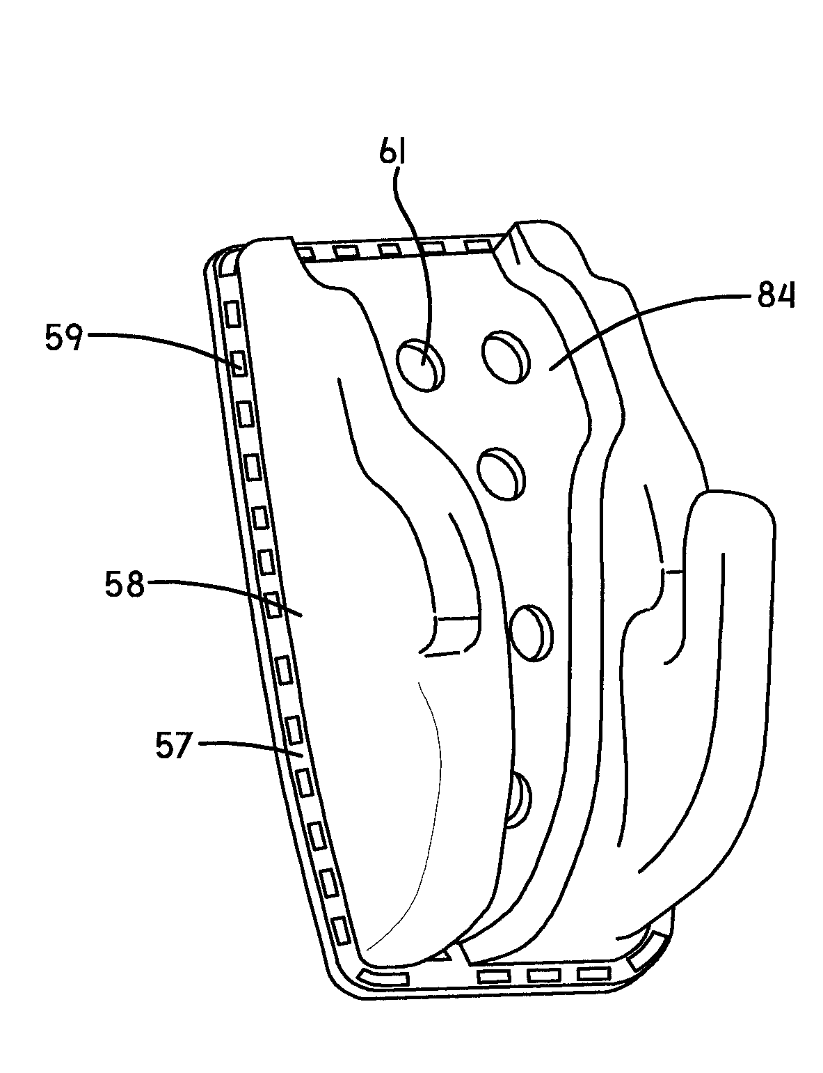
The invention is a wiper lifter assembly for vehicles that includes a wiper ramp, a wiper contact member, and an isolation pad. The wiper ramp is made of a soft material to reduce noise when the wiper is in a park position. The wiper contact member is attached to the ramp to contact the wiper before any other part of the lifter assembly. The isolation pad has two surfaces that make contact with the ramp and the vehicle, respectively. The invention is easy and inexpensive to manufacture. The technical effects of the invention are that it supports the wiper in a park position without unwanted noise and is relatively easy and inexpensive to manufacture.

Problems solved by technology

While known two part wiper lifters generally work well for their intended purpose, they have a disadvantage.
In particular, when wipers are parked onto known wiper lifters a loud “thunk” or “thud” noise occurs.
This noise is undesirable.
A disadvantage, however, is that the wiper lifter 1 is relatively complex and thus relatively expensive to manufacture.

Method used


Image

  • Wiper lifter
  • Wiper lifter
  • Wiper lifter

Examples


Embodiment Construction

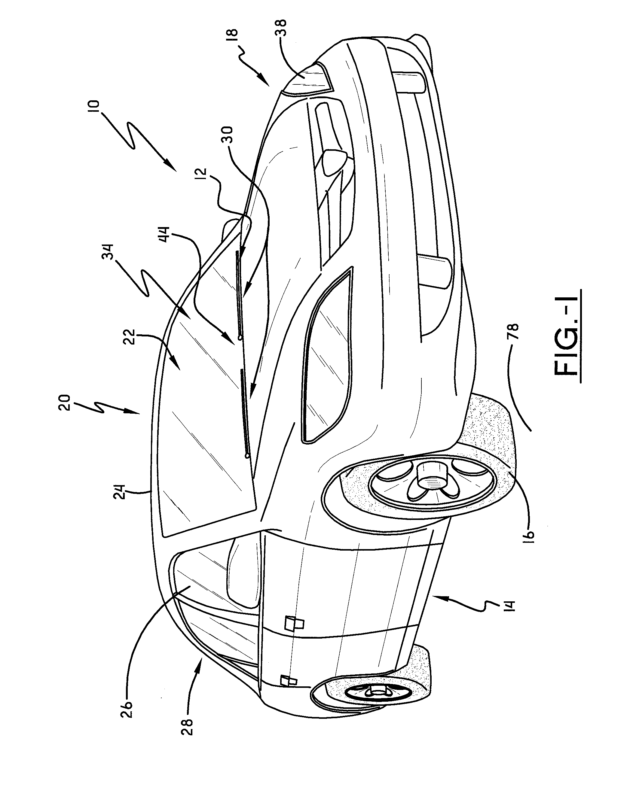
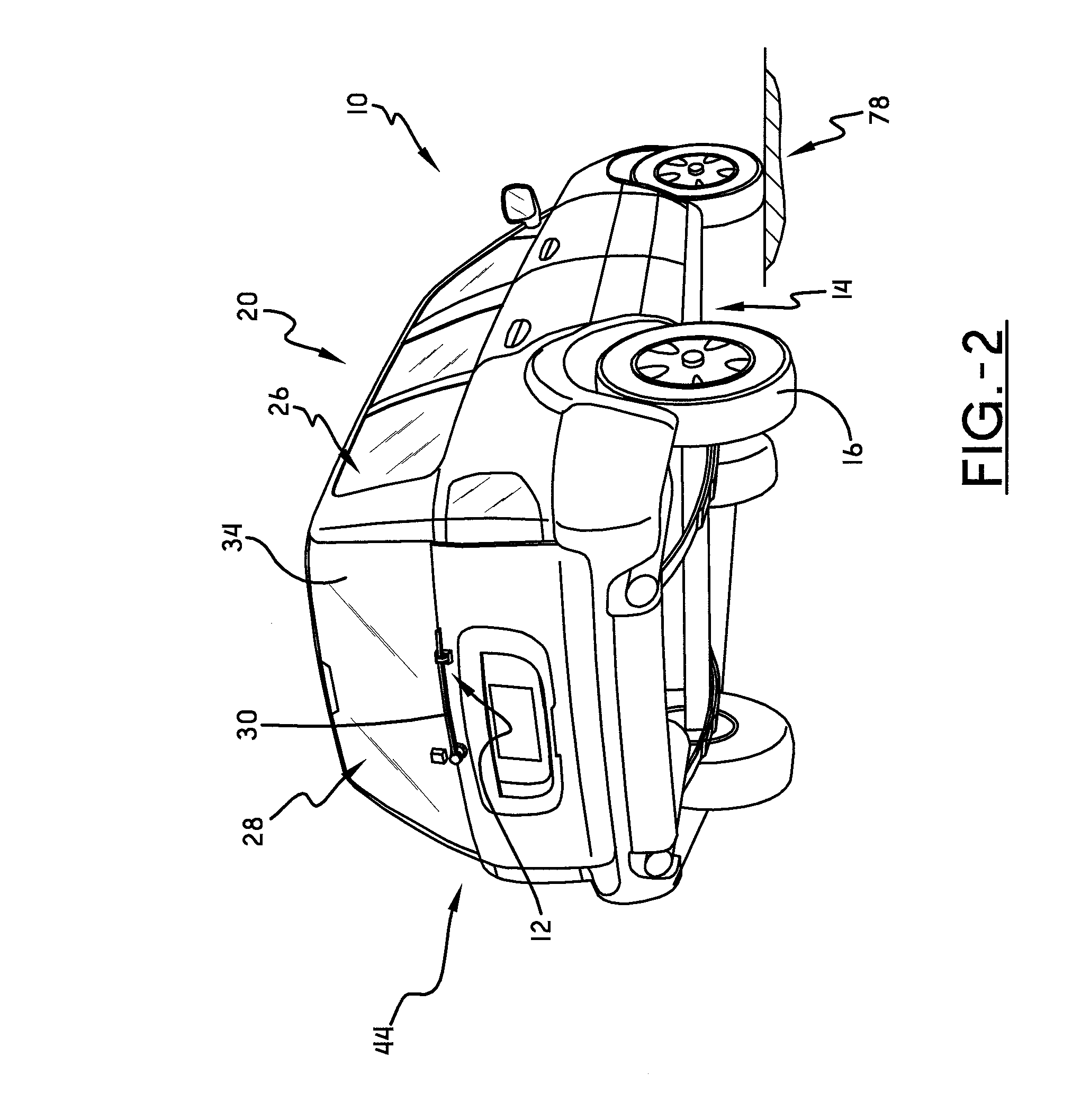
[0028]Referring now to the drawings wherein the showings are for purposes of illustrating embodiments of the invention only and not for purposes of limiting the same, and wherein like reference numerals are understood to refer to like components, FIGS. 1 and 2 each show a vehicle 10 that may be equipped with a wiper lifter assembly 12, according to one embodiment of this invention. While the vehicle 10 shown in FIG. 1 is a sedan and the vehicle shown in FIG. 2 is a sports utility vehicle (SUV), it is to be understood that the wiper lifter assembly 12 of this invention will work with any vehicle including, for some non-limiting examples, cars, trucks, motorcycles, aircraft and sea-faring vessels. The vehicle 10 may include a frame 14, one or more ground engaging wheels 16 mounted to the frame 14, and a locomotion source 18, mounted to the frame 14, for use in providing locomotion for the vehicle 10. The locomotion source could be of any type chosen with the sound judgment of a person...


PUM

PropertyMeasurementUnit
thickness T1aaaaaaaaaa

Abstract

A wiper lifter assembly may include a wiper ramp that lifts a wiper away from a wiper surface on a vehicle, an isolation pad for attaching the assembly to the vehicle, and a wiper contact member that is attached to an upper surface of the wiper ramp. The wiper ramp may be formed of a first material while the wiper contact member and the isolation pad may be both formed of a second material that is softer than the first material.

Description

I. BACKGROUND[0001]A. Field of Invention[0002]This invention pertains to the art of methods and apparatuses related to vehicle surface cleaning and more specifically to methods and apparatus related to windshield wipers.[0003]B. Description of the Related Art[0004]It is well known in the art to provide vehicles with devices commonly referred to as “windshield wipers” that are operated to clean and / or clear the front and sometimes the back window or windshield through which vehicle passengers look. Such windshield wipers are typically pivoted across a portion of the outer surface of the windshield where they clear or wipe the windshield surface to remove water, snow, ice or debris.[0005]It is also well known to place windshield wipers in a non-use or “park” position when they are not being used. Often, the windshield wipers are positioned onto a wiper lifter, sometimes referred to as a ramp, to maintain the wiper in the parked position. Typically, placing the wiper onto the wiper lif...

Claims


Application Information

Patent Timeline
Patent Type & Authority Applications(United States)
IPC IPC(8): B60S1/02B23P17/04
CPCY10T29/49826B60S1/0455
Inventor SCHRADER, MICHAEL A.
Owner HONDA MOTOR CO LTD
Learn More