Property monitoring apparatus for current transformer or electric transformer

a technology of current transformer and monitoring apparatus, applied in the direction of electrical testing, measurement devices, instruments, etc., can solve the problems of inability to directly measure the property of the zero-phase current transformer (zct), the restriction of the use of zero-phase current transformers (zct), and the inability to use other zero-phase current transformers, so as to achieve high accuracy of measurement, improve the accuracy of insulation monitoring apparatus, and facilitate inspection of measurement devices

Inactive Publication Date: 2011-06-23
HITACHI IND EQUIP SYST CO LTD
View PDF5 Cites 32 Cited by
  • Summary
  • Abstract
  • Description
  • Claims
  • Application Information

AI Technical Summary

Benefits of technology

[0019]According to the technical means illustrated in above paragraph (1) of the present invention, upon monitoring the property of a current transformer or a voltage transformer used in a measurement device, an accurate test current value is supplied to the current transformer or the voltage transformer, and based on the relationship between the test current and the output current of the current transformer or the voltage transformer, the present invention enables to obtain an accurate correction coefficient corresponding to the property of the current transformer or the voltage transformer within the monitoring device and to store the same in the storage section of the monitoring device, so that highly accurate measurement can be performed regardless of the properties of the current transformer or the voltage transformer being used.
[0020]According to the technical means illustrated in above paragraph (2) of the present invention, by designing the test current output circuit as an independent body and enabling the same to be connected in a detachable manner to the main body, it becomes possible to store the correction coefficients of multiple measurement devices in the respective property monitoring apparatuses by merely changing the program in the CPU incorporated in the measurement device body.
[0021]According to the technical means illustrated in above paragraph (3) of the present invention, when an inspection mode is selected, a test current having a pattern set in advance is supplied to the current transformer or the voltage transformer even in a no-load state, and by comparing the relationship between the previous test current value and the measurement current value stored in the storage means with the relationship between the present test current value and the measurement current value, the inspection of the measurement device can be performed easily.
[0022]According to the technical means illustrated in above paragraph (4) of the present invention, regardless of the property of the zero-phase current transformer being used in the insulation monitoring apparatus, an accurate correction coefficient corresponding to the property of the zero-phase current transformer (ZCT) can be stored in the storage section of the insulation monitoring apparatus, and the leak current measurement value output by the zero-phase current transformer can be corrected using the correction coefficient, by which the accuracy of the insulation monitoring apparatus can be improved significantly.

Problems solved by technology

However, the zero-phase current transformers (ZCT) that can be used are restricted to those having obtained such correction values in advance.
According to the prior art insulation monitoring apparatus, as described earlier, the zero-phase current transformers (ZCT) as measurement media have respectively varied properties, so that the properties of the respective zero-phase current transformers (ZCT) must be measured in advance and the correction value thereof must be stored in a storage section of the apparatus, and therefore, it is not possible to use zero-phase current transformers other than those having their properties measured in advance.
Further according to the prior art insulation monitoring apparatus, the highly accurately controlled test current is not directly passed through the zero-phase current transformer (ZCT), and therefore, the property of the zero-phase current transformer (ZCT) cannot be directly measured.
Moreover, the prior art apparatus does not allow confirmation of the state of connection regarding the zero-phase current transformer being used and the operation of the leak current detection circuit in a no-load state during periodic inspection.

Method used


Image

  • Property monitoring apparatus for current transformer or electric transformer
  • Property monitoring apparatus for current transformer or electric transformer
  • Property monitoring apparatus for current transformer or electric transformer

Examples


embodiment 1

(Description of Configuration)

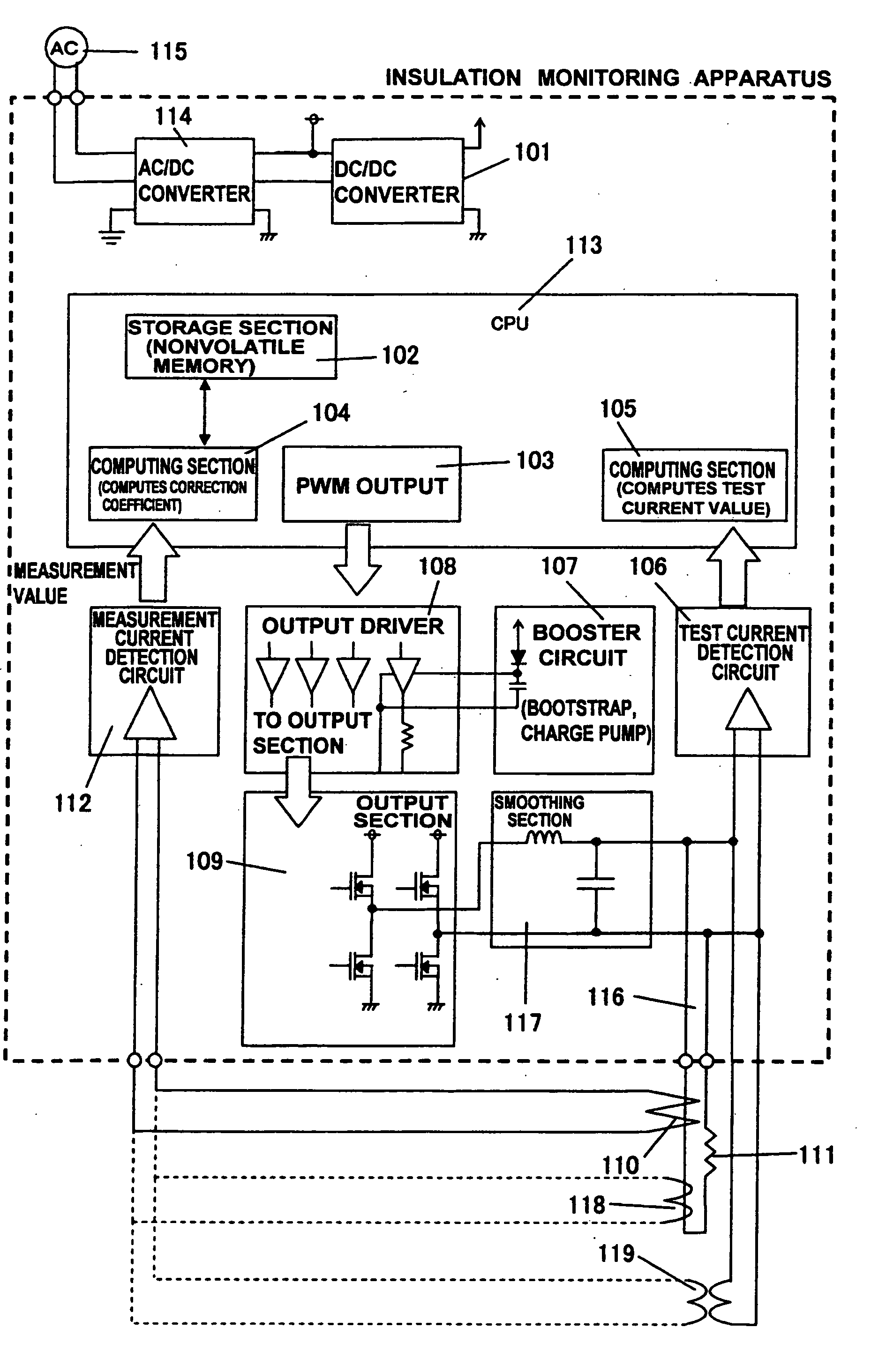
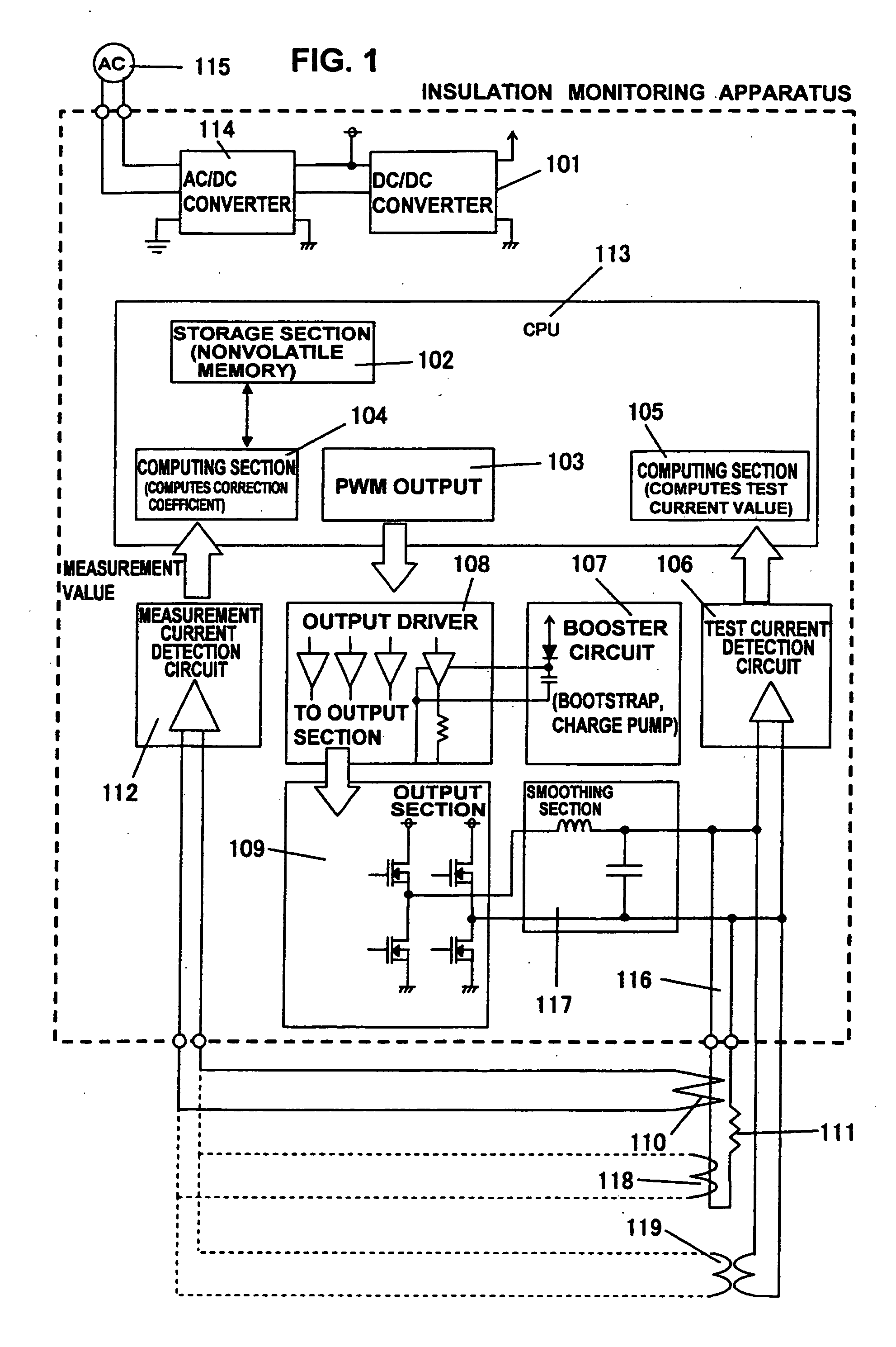
[0028]FIG. 1 shows the overall configuration of an insulation monitoring apparatus.

[0029]The insulation monitoring apparatus is to be installed in an electric power substation or the like, wherein a zero-phase current transformer (ZCT) 110 is disposed on an electric path to be monitored having electric power supplied thereto from a three-phase transformer, for detecting via a measurement current detection circuit 112 a secondary current of the zero-phase current transformer (ZCT) 110 caused by the occurrence of an electric leakage, and based on the detected current value, monitoring the occurrence of electric leakage via the CPU 113.

[0030]The insulation monitoring apparatus includes an AC / DC converter section 114 and a DC / DC converter section 101 for operating the apparatus, and thereby, a DC power supply voltage is generated from a commercial power supply or the like.

[0031]The DC power supply voltage is for operating a CPU 113, an output driver 108, a ...

embodiment 2

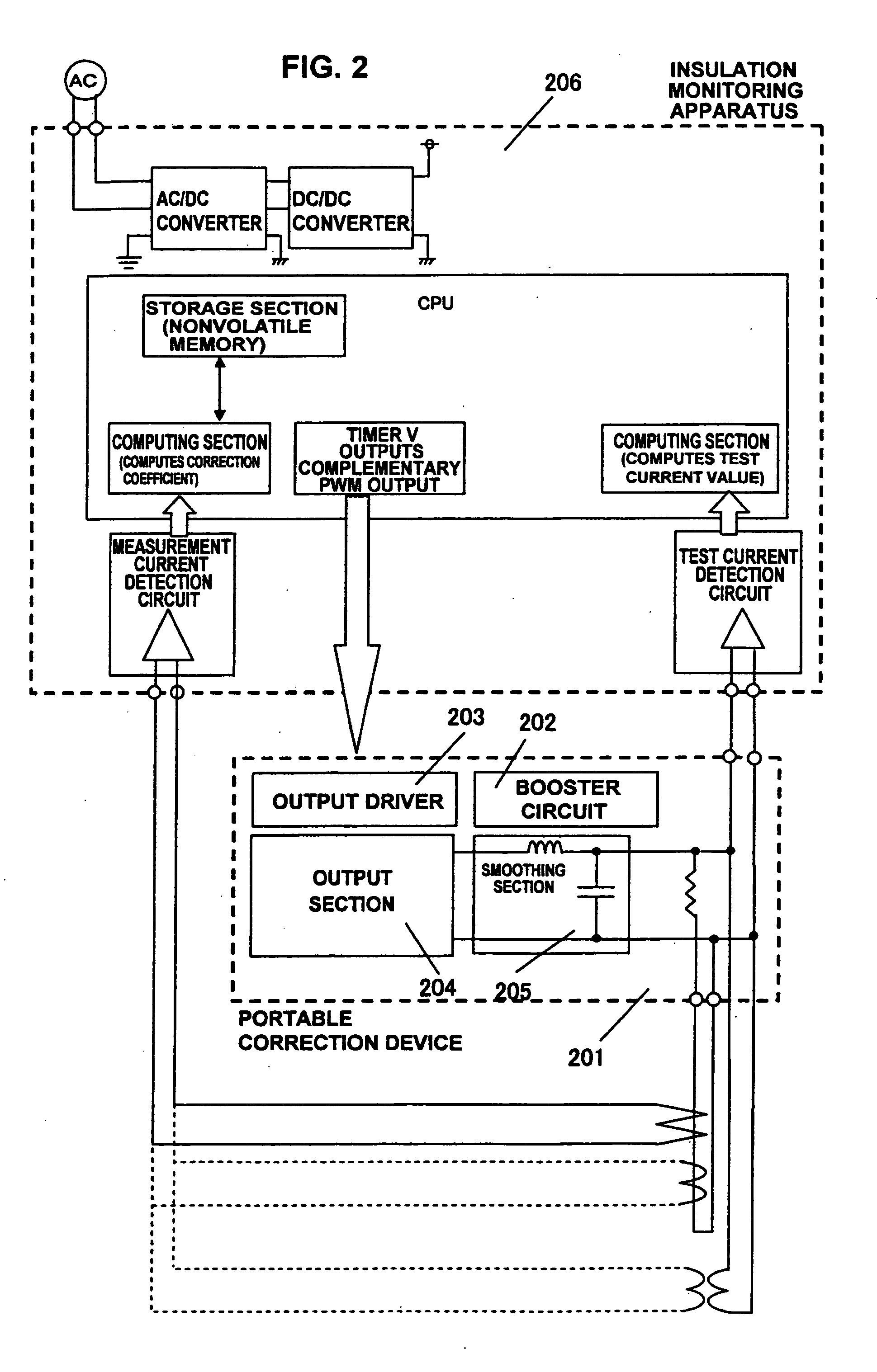
[0062]According to embodiment 1, the output driver 203, the booster circuit 202, the output section 204 and the smoothing section 205 constitute a test current output circuit for outputting a test current of a predetermined effective value in response to the demand from the CPU 113, and the test current output circuit is incorporated in the insulation monitoring apparatus, wherein the PWM output section 103, the computing section 104, the computing section 105 and the like are functions realized via the software of the CPU 113, so the only structure that must be newly disposed as hardware is the test current output circuit.

[0063]Thus, according to embodiment 2, the test current output circuit composed of the output driver 203, the booster circuit 202, the output section 204 and the smoothing section 205 is formed as an independent portable correction device 201, which can be connected to a connecting section formed on the insulation monitoring apparatus only when acquiring the corre...

embodiment 3

[0068]The correction function explained in embodiments 1 and 2 can be used for inspection after installing the insulation monitoring apparatus.

[0069]Since various test currents can be supplied to the insulation monitoring apparatus after installation, even if load is not connected to the main line 304, if the power supply to the load is disconnected, or if leak current is not flown, the operation and the state of connection of the zero-phase current transformer (ZCT) 303 can be confirmed.

[0070]Further, the present correction function can be used for periodic inspection.

[0071]In the example, a switch is disposed on the main body of the insulation monitoring apparatus 301 so as to switch the mode of the apparatus between the aforementioned correction mode and an inspection mode.

[0072]During the inspection mode, a frequency setting parameter is used for changing the PWM output stored in the storage unit, and a test current of a predetermined pattern is supplied from the insulation moni...


PUM


Abstract

The invention provides a property monitoring apparatus comprising a test current output circuit capable of varying an output current, a test current value computing means for computing a current value of a test current output from the test current output circuit, a test current control means for performing feedback control of the test current value computed via the test current value computing means to a target value, a measurement current detection circuit for measuring an output current value of the current transformer or the voltage transformer when the test current controlled to the target value via the test current control means is supplied, for storing a relationship between the output current value of the current transformer or the voltage transformer and the test current value for each target value by varying the target value of the test current via a predetermined pattern, and computing a correction coefficient for correcting a property of the current transformer or the voltage transformer based on the stored relationship.

Description

[0001]The present application is based on and claims priority of Japanese patent application No. 2009-287389 filed on Dec. 18, 2009, the entire contents of which are hereby incorporated by reference.BACKGROUND OF THE INVENTION[0002]1. Field of the Invention[0003]The present invention relates to a property monitoring apparatus for accurately monitoring the property of a current transformer or an electric transformer used for example in a measurement device, such as a zero-phase current transformer (ZCT) used in an insulation monitoring apparatus.[0004]2. Description of the Related Art[0005]Patent document 1 (Japanese patent application laid-open publication No. 2003-215196) and patent document 2 (Japanese patent application laid-open publication No. 2002-289085) disclose arts related to measuring a leak current in an insulation monitoring apparatus using a zero-phase current transformer (ZCT), wherein the output of the zero-phase current transformer (ZCT) is taken in to measure the l...

Claims


Application Information

Patent Timeline
Patent Type & Authority Applications(United States)
IPC IPC(8): G01R31/06
CPCG01R35/02G01R31/027G01R31/62
Inventor SATOU, KOUJIKIMURA, TOSHIKOWATANABE, TETSUNORI
Owner HITACHI IND EQUIP SYST CO LTD
Why Eureka
Try Eureka