
RFID reader, RFID tag, and method of recognizing plurality of RFID tags

Inactive Publication Date: 2011-06-23
ELECTRONICS & TELECOMM RES INST
View PDF18 Cites 4 Cited by
  • Summary
  • Abstract
  • Description
  • Claims
  • Application Information

AI Technical Summary

Benefits of technology

[0007]The present invention is directed to a radio frequency identification (RFID) system and method that reduce collisions among responses of a plurality of tags using a tag grouping scheme and an inter-tag interference removing scheme in addition to a conventional general tag protocol, and thus can increase the number of recognizable tags to several times that of conventional art.
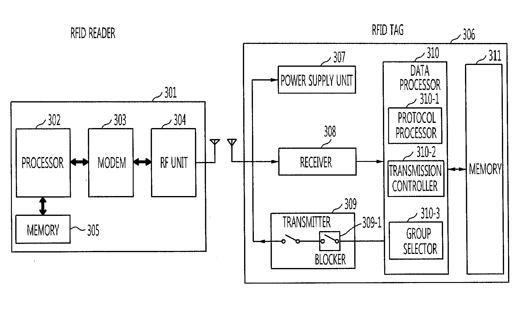
[0010]Still another aspect of the present invention provides a method of recognizing a plurality of RFID tags in an RFID system including: transmitting, at an RFID reader, a group_select command to at least one of the RFID tags; selecting, at the RFID tag, a group number of the RFID tag on the basis of the group_select command; transmitting, at the RFID reader, a wake_group command including an argument specifying a group number to the RFID tag; determining, at the RFID tag, whether or not the group number specified by the wake_group command and the group number of the RFID tag are identical; and disabling a backscattering function of the RFID tag when the specified group number and the group number of the RFID tag are not identical, and enabling the backscattering function of the RFID tag when the specified group number and the group number of the RFID tag are identical.

Problems solved by technology

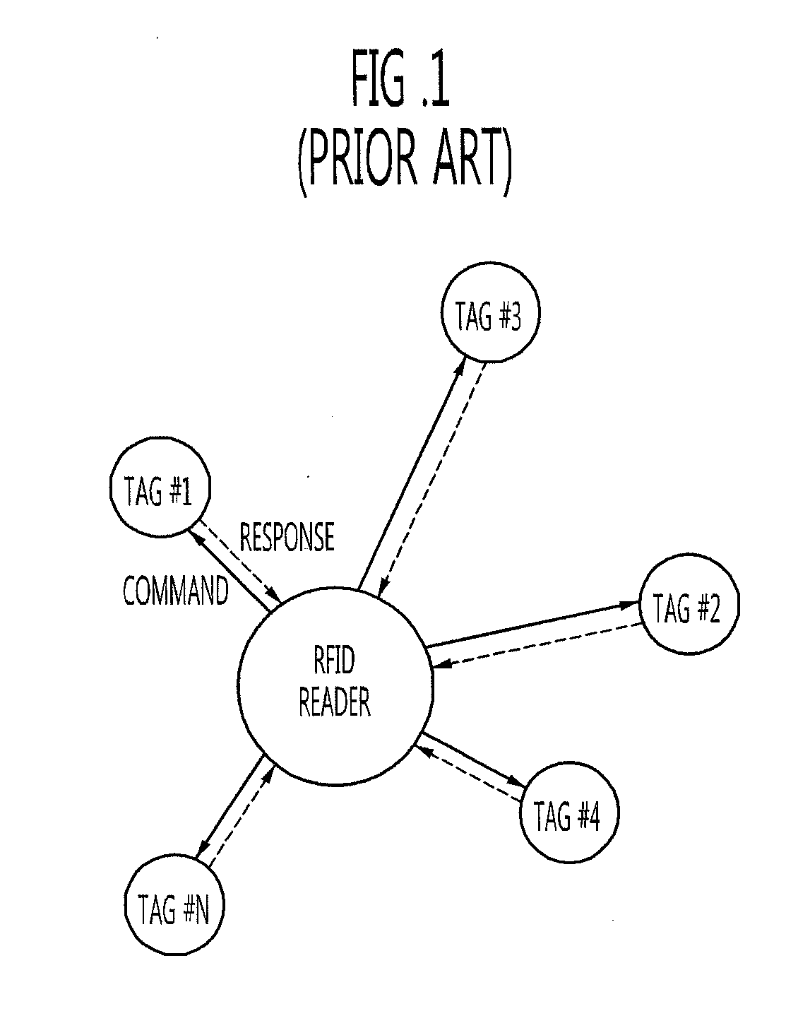
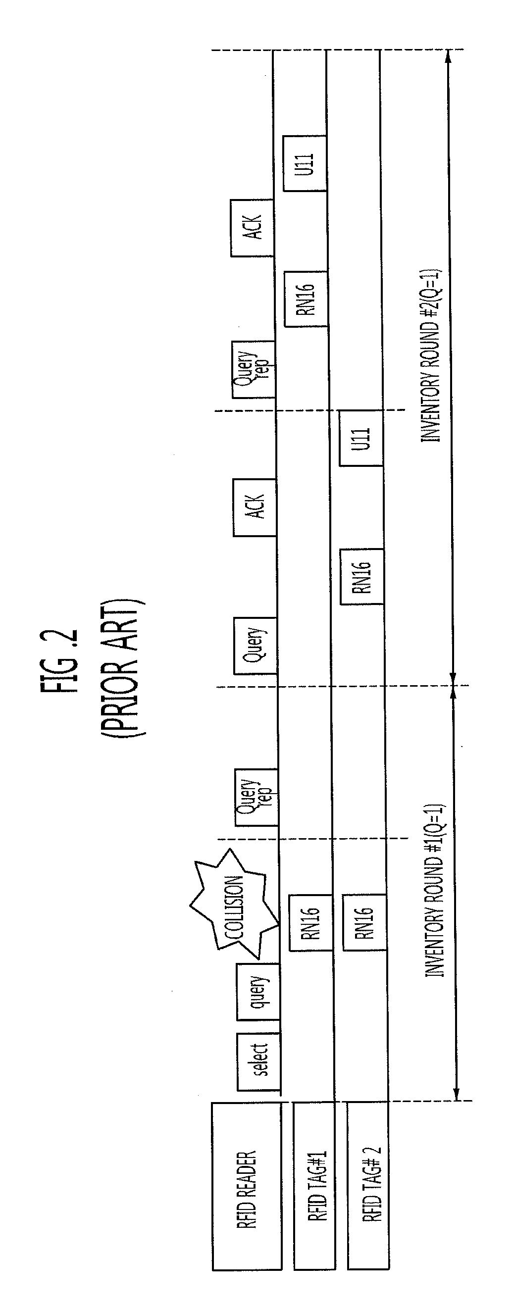
At this time, collisions occur when many tags select the same slot, and backscattering of all the tags interferes with adjacent tags.
As a result, tag recognition time increases, or the number of recognizable tags is limited.

Method used


Image

  • RFID reader, RFID tag, and method of recognizing plurality of RFID tags
  • RFID reader, RFID tag, and method of recognizing plurality of RFID tags
  • RFID reader, RFID tag, and method of recognizing plurality of RFID tags

Examples


Embodiment Construction

[0020]Hereinafter, exemplary embodiments of the present invention will be described in detail. However, the present invention is not limited to the embodiments disclosed below but can be implemented in various forms. The following embodiments are described in order to enable those of ordinary skill in the art to embody and practice the present invention. To clearly describe the present invention, parts not relating to the description are omitted from the drawings. Like numerals refer to like elements throughout the description of the drawings.

[0021]Throughout this specification, when an element is referred to as being “connected” or “coupled” to another element, it can be directly connected or coupled to the other element or electrically connected or coupled to the other element with yet another element interposed between them.

[0022]Throughout this specification, when an element is referred to as “comprises,”“includes,” or “has” a component, it does not preclude another component bu...


PUM


Abstract

The RFID reader of an RFID system includes a processor for processing a command for the RFID tag and a response from the RFID tag, a modem for modulating the command from the processor or demodulating the response from the RFID, and an RF unit for transmitting the modulated command transferred from the modem to the RFID tag or receiving the response from the RFID tag and transferring the response to the modem. The RFID tag of the RFID system includes a power supply unit for generating energy using a radio wave received from the RFID reader, a receiver for demodulating a signal received from the RFID reader, a data processor for performing operation according to the signal demodulated by the receiver, and a transmitter for backscattering a signal from the data processor.

Description

CROSS-REFERENCE TO RELATED APPLICATION[0001]This application claims priority to and the benefit of Korean Patent Application No. 10-2009-0127669, filed Dec. 21, 2009, the disclosure of which is incorporated herein by reference in its entirety.BACKGROUND[0002]1. Field of the Invention[0003]The present invention relates to a radio frequency identification (RFID) reader, an RFID tag, and a method of recognizing a plurality of RFID tags, and more particularly to an RFID system and method which controls a protocol and operation between an RFID reader and a plurality of RFID tags to easily recognize the RFID tags while reducing as much collision among the RFID tags as possible.[0004]2. Discussion of Related Art[0005]In general, RFID technology enables information to be read from or recorded in a tag having unique ID information using an RF without contact, so that an animal, person, etc. to which a tag is attached can be recognized, tracked, and managed. An RFID system includes a pluralit...

Claims


Application Information

Patent Timeline
IPC IPC(8): H04Q5/22
CPCG06K7/10039G06K7/10029G06K17/00H04B5/48
Inventor PARK, CHAN WONPARK, MAN SIKBAE, JI HOONLEE, DONG HANCHO, KWANG SOOCHOI, WON KYUQUAN, CHENG HAOKIM, JEONG SEOKCHOI, GIL YOUNGCHAE, JONG SUK
Owner ELECTRONICS & TELECOMM RES INST
Learn More