Conveyor belt for a treadmill

a conveyor belt and treadmill technology, applied in the field of conveyor belts for treadmills, can solve the problems of different degrees of hardness on the surface area, affecting the stability of the patient walking on the conveyor belt, and the inability to visually adjust to the surface, etc., and achieve the effect of increasing stability

Inactive Publication Date: 2011-06-23
TEO INDDESIGN +1
View PDF22 Cites 27 Cited by
  • Summary
  • Abstract
  • Description
  • Claims
  • Application Information

AI Technical Summary

Benefits of technology

[0016]According to another embodiment it is intended that the conveyor belt have at least two encircling belts spaced apart from each other which are attached to an endless mat having a contoured surface structure which also runs around the entire circumference. A mat of this type made of elastic, flexible material, e.g. PU foam, and having an average height of approx. 10-25 mm, can be guided, having the appropriate elasticity, together with the belts which transport the mat, around the rollers of the treadmill. With a height of between 10-25 mm it is also possible for the contoured surface structure to be noticeable even when running with shoes.
[0017]According to another, third embodiment it is intended that the conveyor belt have a support layer made of textile whereby the support layer has a running surface with a contoured surface structure made of an elastic material, e.g. PU foam. Here too the support surface may have a thickness of between 10 and 25 mm, whereby this embodiment is distinguished from the previously described embodiments in that it exhibits an increased stability because the support layer extends over the entire width of the conveyor belt, as is already known from the prior art in regard to the support layer.

Problems solved by technology

This means that the patient walking on a conveyor belt of this type is unable to visually adjust to the surface.
Furthermore, there is the possibility of structuring the plates such that they have differing degrees of hardness on their surface areas, for example, in that the plates have chambers on their lower surfaces in which inserts can be placed.

Method used


Image

  • Conveyor belt for a treadmill
  • Conveyor belt for a treadmill
  • Conveyor belt for a treadmill

Examples


Embodiment Construction

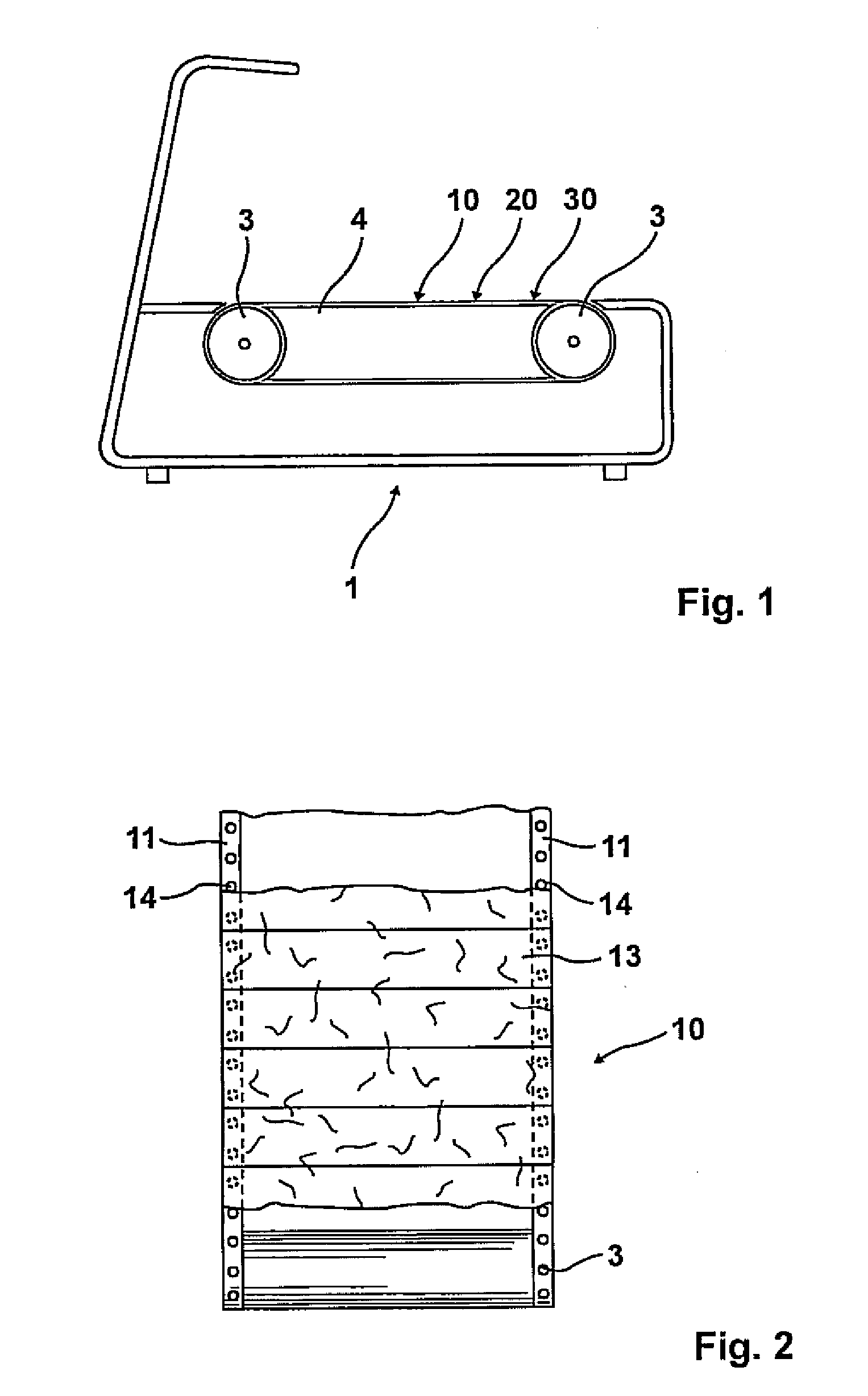
[0026]The treadmill according to FIG. 1, indicated by the numeral 1 has the two rollers 3 around which the conveyor belt, indicated by the numeral 10, runs. Between the two rollers 3 is a platform 4, on which the conveyor belt is supported when weighted by a runner.

[0027]The object of the invention is the construction of the conveyor belt.

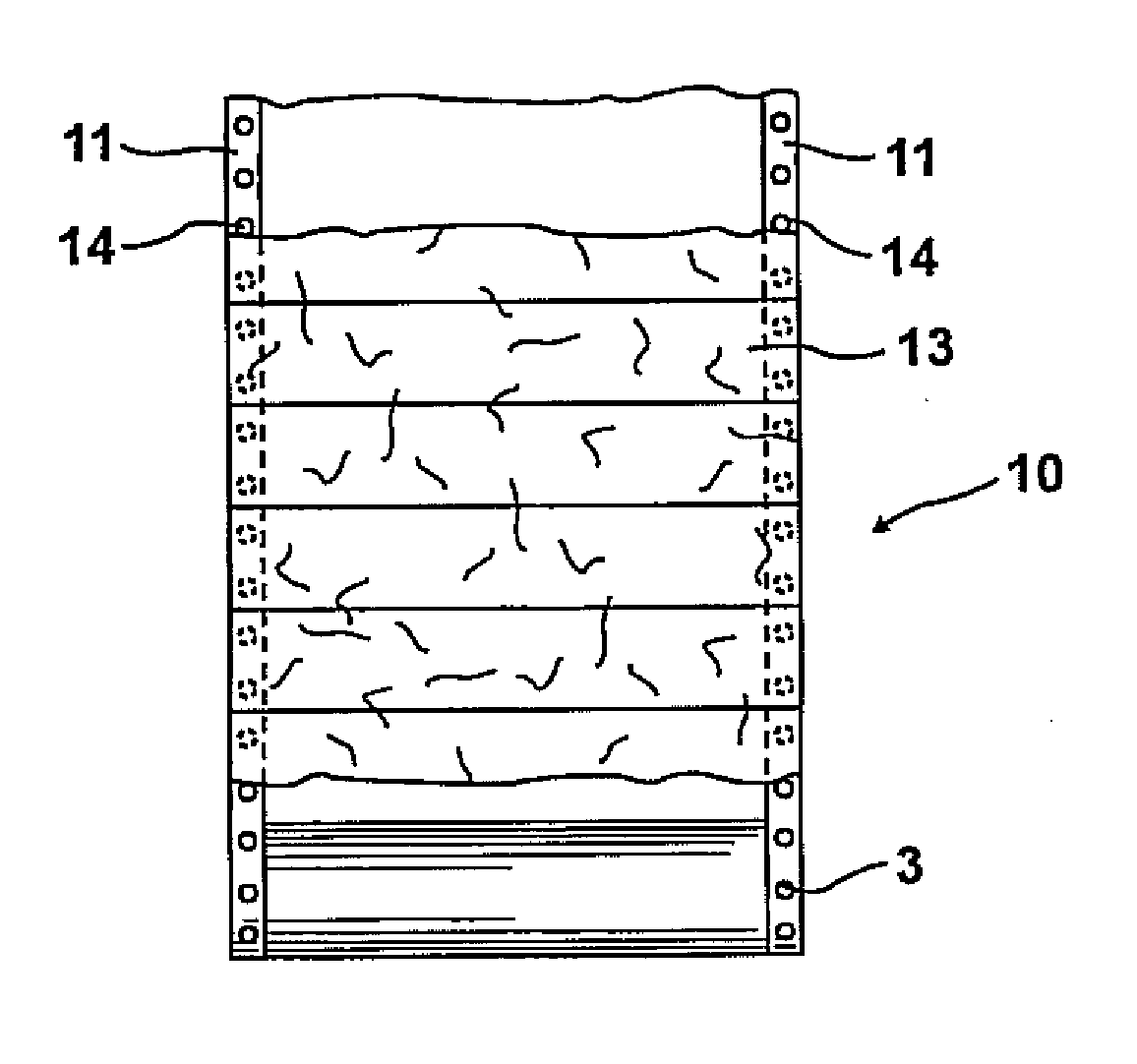
[0028]According to the embodiment in accordance with FIG. 2, the conveyor belt, indicated by the numeral 10 consists of two separate belts 11 which run over the rollers 3, whereby the individual plates 13 are located on the belts 11. The attachment of the plates 13 to the belts is made with, for example, rivets 14.

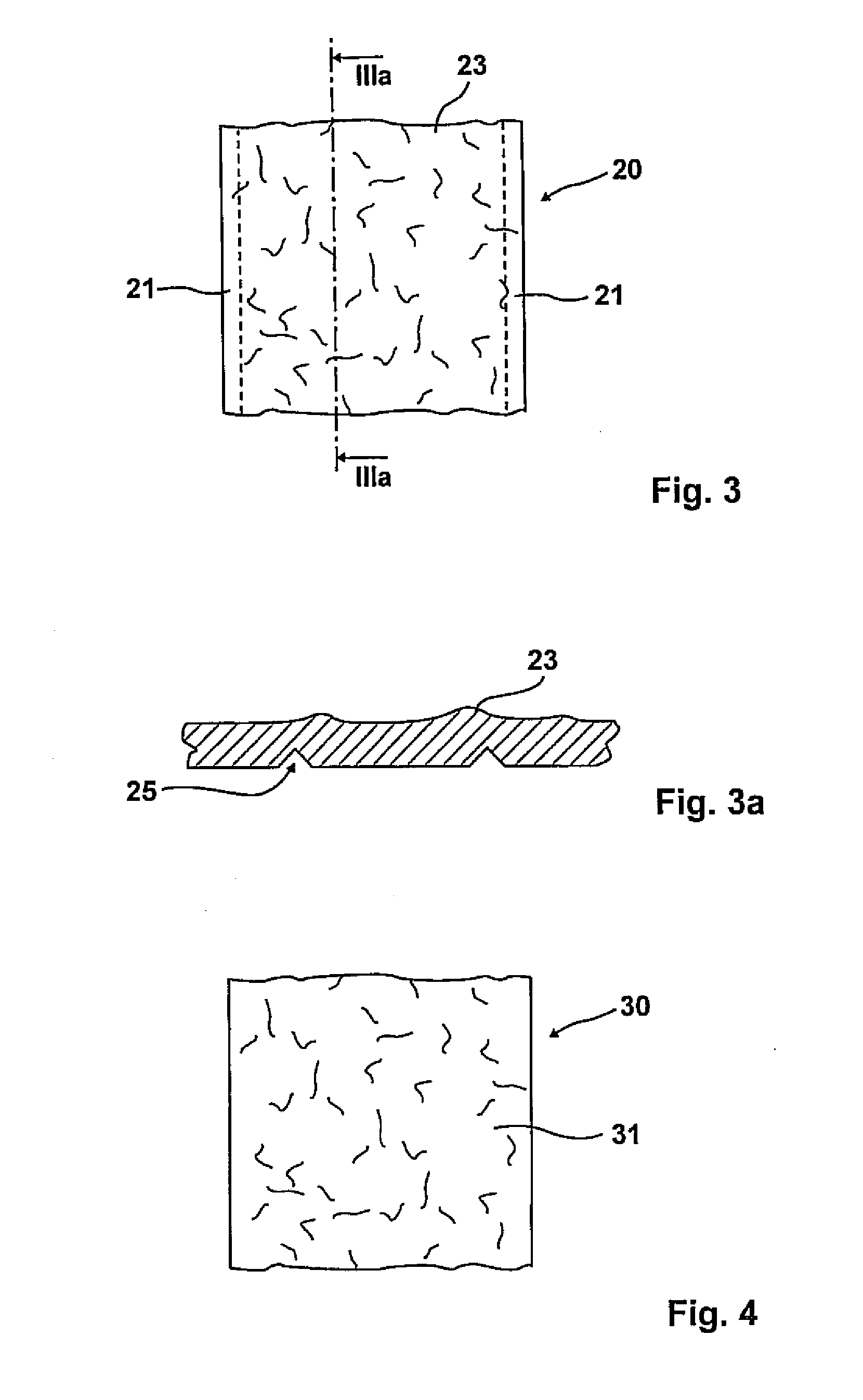
[0029]The plates 13 have a contoured surface structure which is clearly apparent in the illustration of FIG. 5. It is important that for the construction of the contoured surface structure, said contoured surface structure continues in a like manner from one plate to the next. This means that the surface structure, i.e. the contour is con...


PUM


Abstract

A conveyor belt for a treadmill has a contoured structure on its upper surface which causes a runner to experience bumps and depressions when running. The contoured features may be provided by plates attached to the conveyor belt, and/or by inserts placed onto the belt or within chambers defined in the belt. The contoured features may vary in hardness.

Description

CROSS-REFERENCE TO RELATED APPLICATIONS[0001]This application claims priority of German Patent Application DE 20 2009 017 334.8 filed Dec. 21, 2009, which is incorporated herein by reference.FIELD OF THE INVENTION[0002]The invention concerns a conveyor belt for a treadmill.BACKGROUND OF THE INVENTION[0003]Treadmills are exercise machines having a conveyor belt running over two rollers arranged at a distance from one another. The speed of the conveyor belt can be adjusted. Treadmills of this type are used to achieve, or respectively, maintain physical fitness.[0004]The known conveyor belts for treadmills have two belts separated from one another, whereby the belts encircle two rollers which are arranged at a distance from one another. The two belts which are separated from one another accommodate numerous plates which are arranged consecutively in such a manner that they basically form a closed running surface. The plates which are, for example, glued or riveted to the belts are appr...

Claims


Application Information

Patent Timeline
Patent Type & Authority Applications(United States)
IPC IPC(8): A63B22/02
CPCA63B22/02A63B2022/0228A63B22/0285A63B22/0235A63B22/0228
Inventor FREITAG, JENS
Owner TEO INDDESIGN
Why Eureka
Try Eureka