Cooperative Calibration of Heading Sensors

a technology of heading sensors and calibration methods, applied in the field of heading sensors, can solve the problems of inability to remove measurement noise from magnetic and inertial sensors, and the drift of gyroscopes ofinertial sensors, and achieve the effect of accurate and simple us

Active Publication Date: 2011-06-23
RAYTHEON CO
View PDF15 Cites 30 Cited by
  • Summary
  • Abstract
  • Description
  • Claims
  • Application Information

AI Technical Summary

Benefits of technology

[0013]In another embodiment, the primary device also includes a range finder. A laser range finder (LRF) mounted so that it measures range along the same axis as the optical sighting system can be used to automatically calculate the location of a target. The primary device measures its lo

Problems solved by technology

Inertial sensors suffer from drift of the gyroscopes over time.
Both magnetic and

Method used


Image

  • Cooperative Calibration of Heading Sensors
  • Cooperative Calibration of Heading Sensors
  • Cooperative Calibration of Heading Sensors

Examples


Embodiment Construction

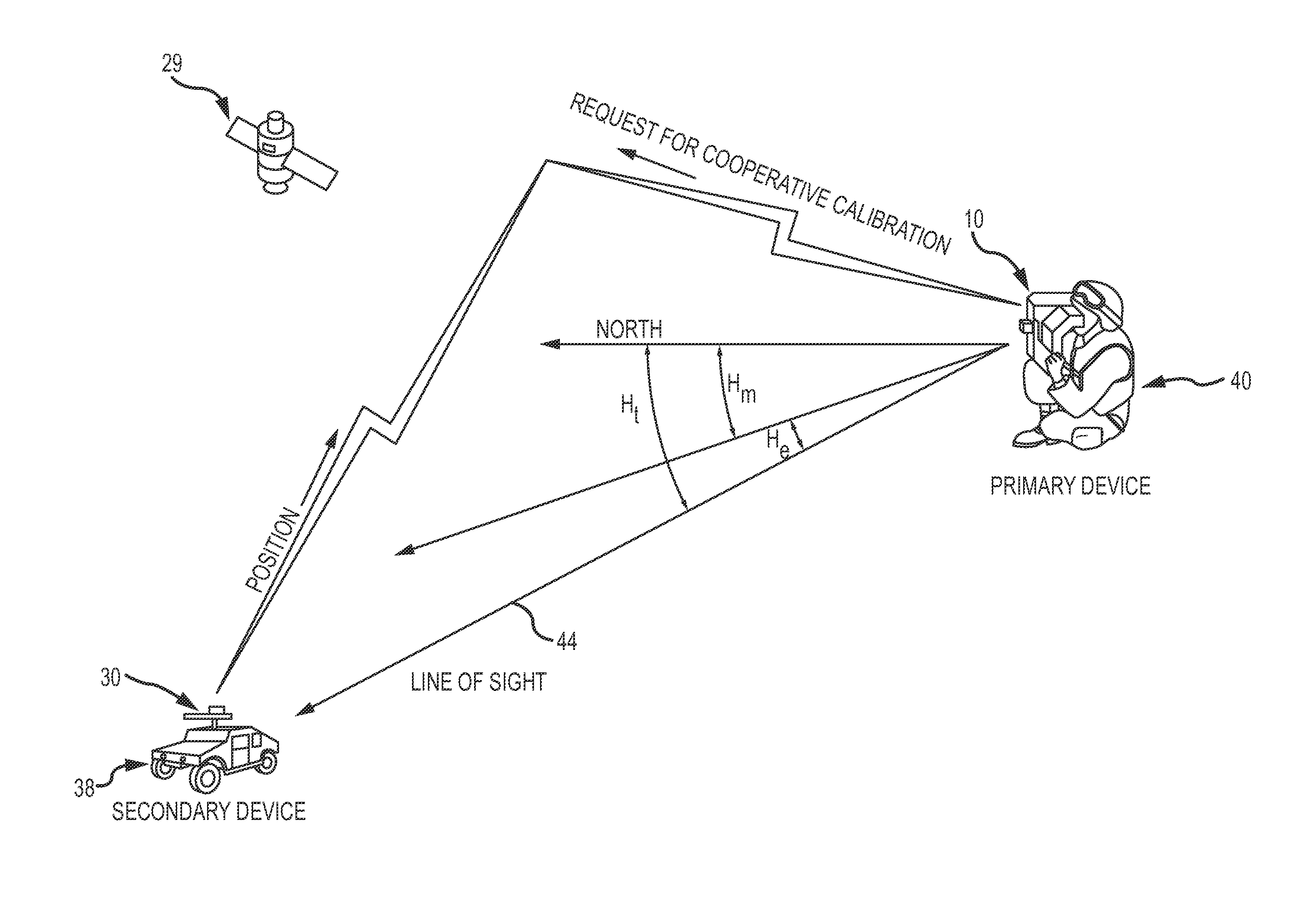
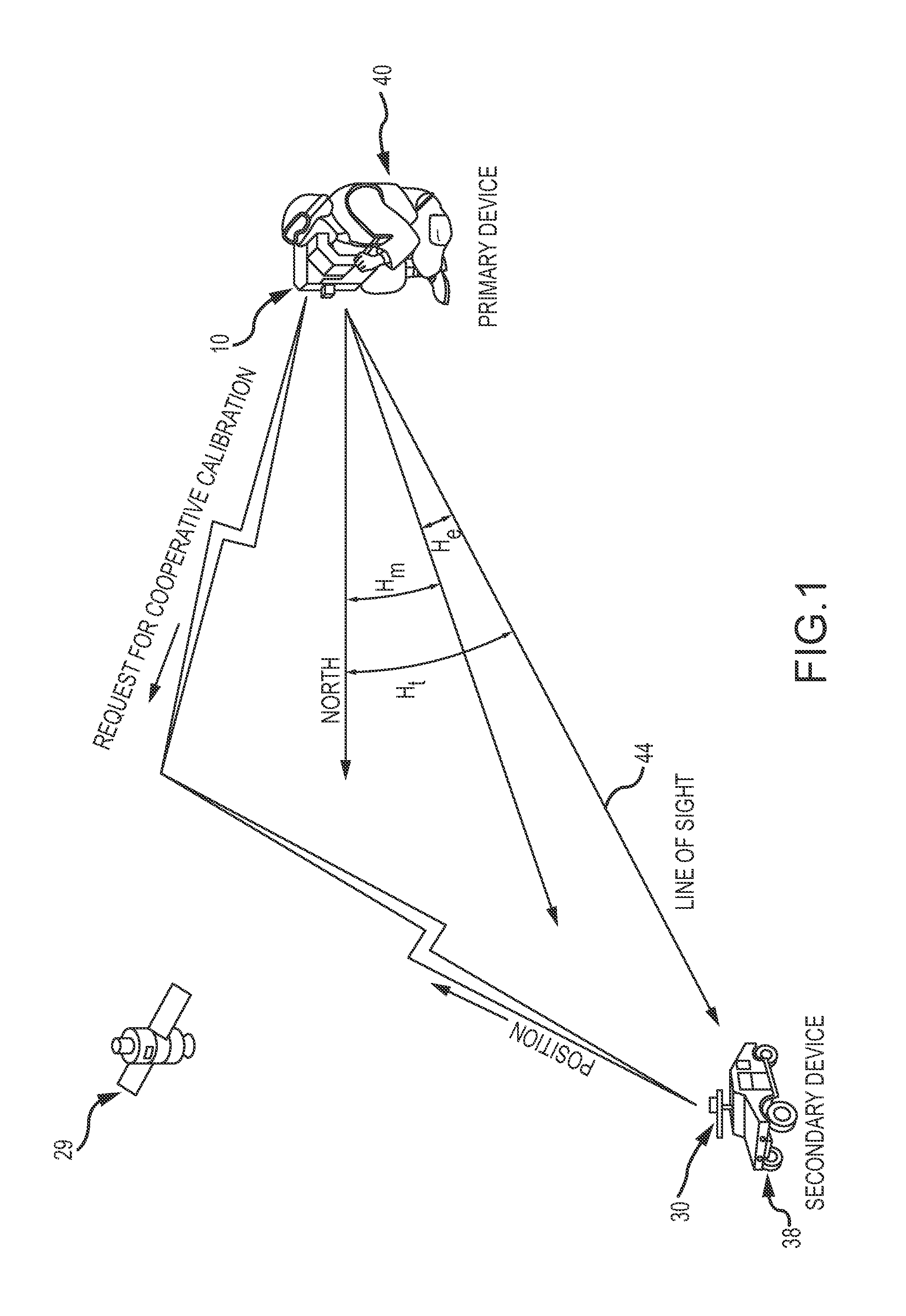
[0024]The present invention describes a system and method of calibration of a heading sensor. The approach is sensor agnostic in that it may be used with any configuration of a magnetic, inertial or hybrid heading sensor. The approach is simple and efficient, simultaneously compensating for multiple sources of measurement error in a single calibration procedure with minimal demands placed on the operator. The approach is effective for both simple compass configurations to determine current heading and for more sophisticated heading sensor that must precisely measure heading and pitch as part of a far target locator for a weapons platform.

[0025]The approach is based on the concept of “cooperative calibration” between the primary device that includes the heading sensor being calibrated and a secondary device. The secondary device cooperates by measuring its Earth relative position and transmitting the position to the primary device. The primary device calculates a true heading from th...


PUM

PropertyMeasurementUnit
Angleaaaaaaaaaa
Longitudeaaaaaaaaaa
Magnetic fieldaaaaaaaaaa

Abstract

A primary device that includes a heading sensor and a remote secondary device cooperate to calibrate the heading sensor. The secondary device cooperates by measuring its Earth relative position and transmitting the position to the primary device. The primary device calculates a true heading from the positions of both devices and subtracts the true heading from a measured heading to the secondary device to form a heading calibration angle. The process may be extended to calculate a pitch calibration angle.

Description

BACKGROUND OF THE INVENTION[0001]1. Field of the Invention[0002]This invention relates to heading sensors, and more particularly to the calibration of heading sensors.[0003]2. Description of the Related Art[0004]Heading sensors are used in a variety of applications such as personal handheld devices, automobiles, airplanes and boats. Heading sensors typically indicate a heading relative to true North although other references are also possible. The heading is typically specified as an azimuth angle from true North. Multi-dimensional sensors may also provide a pitch measurement. Pitch is typically specified as an elevation angle from the local level.[0005]Heading sensors include magnetic compasses that sense the Earth's magnetic field and inertial compasses that exploit the Earth's rotation. A simple magnetic compass includes a magnetized pointer usually marked on the North end free to align itself with the Earth's magnetic field. A compensation, typically in the form of a declination...

Claims


Application Information

Patent Timeline
IPC IPC(8): G01P21/00G01S19/51
CPCG01C17/38G01C25/005G01C19/38
Inventor BAILEY, MICHAEL B
Owner RAYTHEON CO
Why Eureka
Try Eureka